MAIN POWER CANNOT SWITCH OFF


id300300000700


Outline

Malfunction symptom

Main power cannot switch OFF

Description
•  While the main power is switched ON (READY on), the main power cannot switch OFF even if the power switch is operated.
•  The power switch POWER indicator light turns on even when the main power is switched OFF.
•  The instrument cluster indication does not disappear even when the main power is switched OFF.
Possible cause
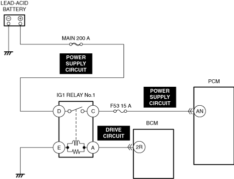
The PCM receives a mistaken main power status signal from the body control module (BCM).
•  Short to power supply in IG1 power supply circuit
•  Short to power supply in IG1 relay drive circuit
The body control module (BCM) does not recognize the power switch operation:
•  Power switch signal circuit malfunction (perform troubleshooting procedure [PUSH BUTTON START SYSTEM DOES NOT OPERATE] of security and Locks symptom troubleshooting)
―  Short to power supply in power switch signal circuit
―  Open circuit in power switch signal circuit
•  Power switch malfunction
•  Body control module (BCM) malfunction
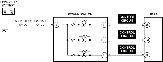
Power switch POWER indicator light false illumination:
•  Power switch POWER indicator light control circuit malfunction
―  Short to ground in power switch POWER indicator light control circuit
•  Body control module (BCM) malfunction
System wiring diagram
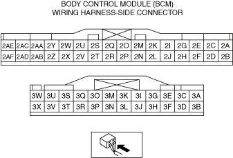
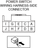
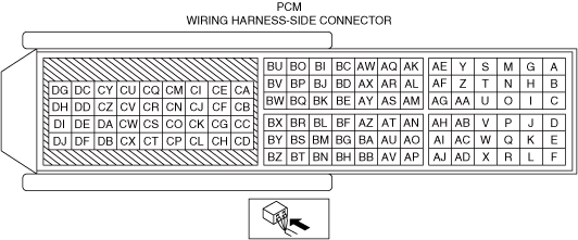
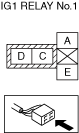
Connector diagram


Diagnostic Procedure

Step

Inspection

Results

Action

1
VERIFY DTCs
•  Perform the DTC inspections for the following modules.
―  PCM
―  Body control module (BCM)
•  Is a DTC displayed?
Yes
Repair the malfunctioning location according to the applicable DTC troubleshooting.
No
Go to the next step.
2
INSPECT IG1 RELAY NO. 1 FOR MALFUNCTION
•  Inspect the applicable part.
•  Is the part normal?
Yes
Go to the next step.
No
Repair or replace the malfunctioning location and perform the repair completion verification.
3
INSPECT PCM IG1 POWER SUPPLY CIRCUIT FOR SHORT TO POWER SUPPLY
•  Inspect the applicable circuit for a short to power supply.
•  Is the circuit normal?
Yes
Go to the next step.
No
Repair or replace the malfunctioning location and perform the repair completion verification.
4
VERIFY PUSH BUTTON START SYSTEM OPERATION
•  Perform the troubleshooting procedure according to the symptom troubleshooting for [PUSH BUTTON START SYSTEM DOES NOT OPERATE] of the security and locks.
•  Is the troubleshooting result normal?
Yes
Go to the next step.
No
Repair or replace the malfunctioning location and perform the repair completion verification.
5
INSPECT POWER SWITCH INDICATOR FOR MALFUNCTION
•  Inspect the applicable part.
•  Is the part normal?
Yes
Go to the next step.
No
Repair or replace the malfunctioning location and perform the repair completion verification.
6
INSPECT POWER SWITCH POWER INDICATOR LIGHT CONTROL CIRCUIT IN POWER SWITCH FOR SHORT TO GROUND
•  Inspect the applicable circuit for a short to ground.
•  Is the circuit normal?
Yes
Go to the next step.
No
Repair or replace the malfunctioning location and perform the repair completion verification.
Repair completion verification
VERIFY THAT VEHICLE IS REPAIRED
•  Install/connect the part removed/disconnected during the troubleshooting procedure.
•  Has the malfunction symptom been eliminated?
Yes
Complete the symptom troubleshooting. (Explain contents of repair to customer)
No
Refer to the CAN (controller area network) malfunction diagnosis flow to inspect for a CAN communication error.