CHARGE PORT ILLUMINATION DOES NOT TURN ON
id300300002200
Outline
Malfunction symptom |
Charge port illumination does not turn on |
|
---|---|---|
Description
|
• The charge port illumination does not turn on when the charge lid is opened.
|
|
Possible cause
|
Charge port illumination circuit malfunction:
• PCM detects DTCs
• Charge lid open/close sensor signal open circuit
• Short to ground in charge lid open/close sensor signal
• Short to power supply in charge lid open/close sensor signal
• Short circuit between charge lid open/close sensor signal circuit and ground circuit
• Open circuit in charge lid open/close sensor ground circuit
• Short to power supply in charge lid open/close sensor ground circuit
• Charge lid open/close sensor malfunction
• Charge port illumination malfunction
|
|
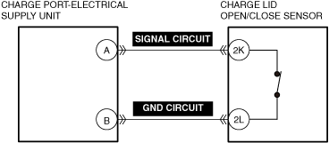
System wiring diagram
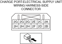
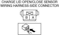
|
![]() |
|
Connector diagram
|
![]() |
![]() |
Diagnostic Procedure
Step |
Inspection |
Results |
Action |
---|---|---|---|
1
|
VERIFY PCM DTCs
• Perform the DTC inspection for the PCM.
(See DTC INSPECTION.)
• Are charge port illumination related DTCs displayed?
|
Yes
|
Repair the malfunctioning location according to the applicable DTC troubleshooting.
(See DTC TABLE [PCM (e-SKYACTIV)].)
|
No
|
Go to the next step.
|
||
2
|
VERIFY OPEN/SHORT CIRCUIT IN CHARGE LID OPEN/CLOSE SENSOR SIGNAL CIRCUIT
• Inspect the applicable circuit for a short circuit or an open circuit.
(See CIRCUIT INSPECTION.)
• Is the circuit normal?
|
Yes
|
Go to the next step.
|
No
|
Repair or replace the malfunctioning location and perform the repair completion verification.
|
||
3
|
VERIFY SHORT CIRCUIT BETWEEN CHARGE LID OPEN/CLOSE SENSOR SIGNAL CIRCUIT AND GROUND CIRCUIT
• Inspect the applicable circuits for a short to each other.
(See CIRCUIT INSPECTION.)
• Is the circuit normal?
|
Yes
|
Go to the next step.
|
No
|
Repair or replace the malfunctioning location and perform the repair completion verification.
|
||
4
|
VERIFY OPEN/SHORT CIRCUIT IN CHARGE LID OPEN/CLOSE SENSOR GROUND CIRCUIT
• Inspect the applicable circuit for a short circuit or an open circuit.
(See CIRCUIT INSPECTION.)
• Is the circuit normal?
|
Yes
|
Go to the next step.
|
No
|
Repair or replace the malfunctioning location and perform the repair completion verification.
|
||
5
|
VERIFY MALFUNCTION IN CHARGE LID OPEN/CLOSE SENSOR
• Inspect the applicable part.
• Is the part normal?
|
Yes
|
Go to the next step.
|
No
|
Replace the malfunctioning location and perform the repair completion verification.
|
||
6
|
INSPECT CHARGE PORT ILLUMINATION FOR MALFUNCTION
• Inspect the applicable part.
• Is the part normal?
|
Yes
|
Go to the next step.
|
No
|
Replace the malfunctioning location and perform the repair completion verification.
|
||
Repair completion verification
|
VERIFY THAT VEHICLE IS REPAIRED
• Install/connect the part removed/disconnected during the troubleshooting procedure.
• Has the malfunction symptom been eliminated?
|
Yes
|
Complete the symptom troubleshooting. (Explain repair contents to customer.)
|
No
|
Refer to the CAN (controller area network) malfunction diagnosis flow to inspect for a CAN communication error.
|