1. : Mazda SST number
2. : Global SST number
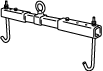
1: 49 UN30 3050
2: 303–050
Engine lifting bracket
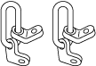
1: 49 L017 5A0
2: –
Support hanger
ENGINE DISASSEMBLY/ASSEMBLY [SKYACTIV-G 2.0]
id0110h2950900
Special Service Tool (SST)
|
1. : Mazda SST number
2. : Global SST number
|
|||
|
1: 49 UN30 3050
2: 303–050
Engine lifting bracket
|
|
1: 49 L017 5A0
2: –
Support hanger
|
|
Replacement Part
|
Gasket
Quantity: 1
Location of use: Oil filter body
|
Gasket
Quantity: 1
Location of use: Water outlet component
|
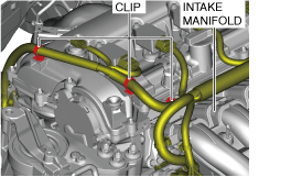
1. To enable to install the SST, disconnect the clip shown in the figure and set the wiring harness aside.
a30zzw00007397
|
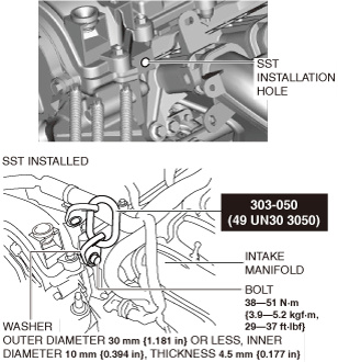
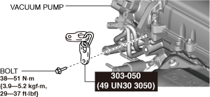
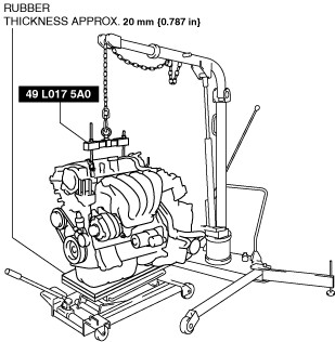
2. Install the SST and the following bolt to the position shown in the figure.
Engine front side
a30zzw00007398
|
Engine rear side
am3zzw00032391
|
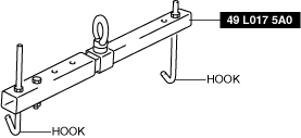
3. Engage the hooks of the SST (49 L017 5A0) to the SST (49 UN30 3050).
am3zzw00025225
|
4. To ensure the safety of the work (control engine and transaxle sway), set a hoist as shown in the figure.
a30zzw00007399
|
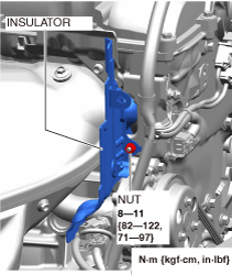
5. Remove the insulator shown in the figure.
a30zzw00005582
|
6. Remove the exhaust system. (See EXHAUST SYSTEM REMOVAL/INSTALLATION [SKYACTIV-G 2.0].)
7. Remove the exhaust manifold bracket No.1. (See Exhaust Manifold Bracket No.1 Removal Note.)(See Exhaust Manifold Bracket No.1 Installation Note.)
8. Remove the bracket No.1 (drive shaft bracket). (See FRONT DRIVE SHAFT REMOVAL/INSTALLATION.)
9. Remove the starter. (See STARTER REMOVAL/INSTALLATION [SKYACTIV-G 2.0].)
10. Remove the coolant control valve. (See COOLANT CONTROL VALVE REMOVAL/INSTALLATION [SKYACTIV-G 2.0].)
11. Fix the drive plate using the crankshaft pulley lock bolt. (ATX)
12. Remove the torque converter installation nut from the starter installation hole. (See AUTOMATIC TRANSAXLE REMOVAL/INSTALLATION [ET6A-EL](2WD).)(See AUTOMATIC TRANSAXLE REMOVAL/INSTALLATION [ET6AX-EL](AWD).)
13. Disconnect the engine and transaxle, and lower only the engine from the engine lifter. (See AUTOMATIC TRANSAXLE REMOVAL/INSTALLATION [ET6A-EL](2WD).)(See AUTOMATIC TRANSAXLE REMOVAL/INSTALLATION [ET6AX-EL](AWD).)
14. Remove the integrated starter generator (ISG). (See INTEGRATED STARTER GENERATOR (ISG) REMOVAL/INSTALLATION.)
15. Remove the intake-air system. (See INTAKE-AIR SYSTEM REMOVAL/INSTALLATION [SKYACTIV-G 2.0].)
16. Remove the oil separator. (See POSITIVE CRANKCASE VENTILATION (PCV) VALVE REMOVAL/INSTALLATION [SKYACTIV-G 2.0].)
17. Remove the knock sensor (KS). (See KNOCK SENSOR (KS) REMOVAL/INSTALLATION [SKYACTIV-G 2.0].)
18. Remove the fuel injectors. (See FUEL INJECTOR REMOVAL/INSTALLATION [SKYACTIV-G 2.0].)
19. Remove the camshaft position (CMP) sensor. (See CAMSHAFT POSITION (CMP) SENSOR REMOVAL/INSTALLATION [SKYACTIV-G 2.0].)
20. Remove the high pressure fuel pump and rear housing. (See HIGH PRESSURE FUEL PUMP REMOVAL/INSTALLATION [SKYACTIV-G 2.0].)
21. Remove the electric variable valve timing motor/driver. (See ELECTRIC VARIABLE VALVE TIMING MOTOR/DRIVER REMOVAL/INSTALLATION [SKYACTIV-G 2.0].)
22. Remove the oil filter. (See OIL FILTER REPLACEMENT [SKYACTIV-G 2.0].)
23. Remove the engine oil solenoid valve. (See ENGINE OIL SOLENOID VALVE REMOVAL/INSTALLATION [SKYACTIV-G 2.0].)
24. Remove the engine oil temperature sensor/engine oil pressure sensor. (See ENGINE OIL TEMPERATURE SENSOR/ENGINE OIL PRESSURE SENSOR REMOVAL/INSTALLATION [SKYACTIV-G 2.0].)
25. Remove the crankshaft position (CKP) sensor. (See CRANKSHAFT POSITION (CKP) SENSOR REMOVAL/INSTALLATION [SKYACTIV-G 2.0].)
26. Remove the dipstick.
27. Remove the ignition coil/ion sensors. (See IGNITION COIL/ION SENSOR REMOVAL/INSTALLATION [SKYACTIV-G 2.0].)
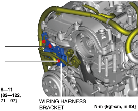
28. Remove the wiring harness bracket shown in the figure.
am3zzw00025228
|
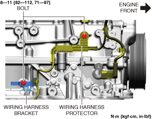
29. Remove the wiring harness bracket and wiring harness protector shown in the figure.
am6xuw00010481
|
30. Remove the emission harness.
31. Remove the water pump drive belt. (See DRIVE BELT REMOVAL/INSTALLATION [SKYACTIV-G 2.0].)
32. Remove the water inlet pipe and flange component. (See CYLINDER HEAD GASKET REPLACEMENT [SKYACTIV-G 2.0].)
33. Remove the water pump. (See WATER PUMP REMOVAL/INSTALLATION [SKYACTIV-G 2.0].)
34. Remove the short cord of the engine oil level sensor. (See ENGINE OIL LEVEL SENSOR REMOVAL/INSTALLATION [SKYACTIV-G 2.0].)
35. Remove in the order indicated in the table.
36. Assemble in the reverse order of disassembly.
Exhaust side
am3zzw00025229
|
|
1
|
Oil filter body
|
|
2
|
Exhaust manifold bracket No.2
|
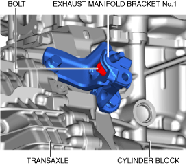
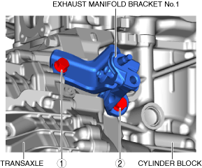
Exhaust Manifold Bracket No.1 Removal Note
1. Loosen the bolt shown in the figure.
am3zzw00032392
|
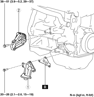
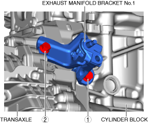
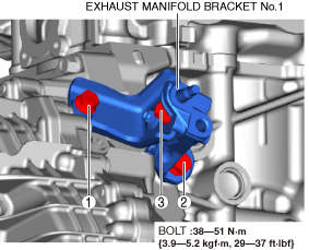
2. Remove the bolts in the order shown in the figure, then remove the exhaust manifold bracket No.1.
am3zzw00032393
|
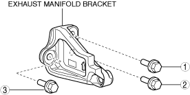
Exhaust Manifold Bracket No.2 Installation Note
1. Temporarily tighten the exhaust manifold bracket installation bolts.
2. Tighten the bolt in the order shown in the figure.
ac5uuw00006901
|
Oil Filter Body Installation Note
1. After tightening the three bolts, tighten the first tightened bolt to the specified tightening torque again.
Exhaust Manifold Bracket No.1 Installation Note
1. Temporarily tighten the exhaust manifold bracket No.1 installation bolts in the order shown in the figure.
am3zzw00032394
|
2. Loosen the bolt shown in the figure until it is no longer seated on the surface.
am3zzw00032392
|
3. Tighten the bolts in the order shown in the figure.
am3zzw00032395
|