|
1
|
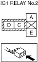
INSPECT IG1 RELAY No.2
• Switch the ignition OFF.
• Disconnect the negative battery terminal.
• Remove the IG1 relay No.2.
• Inspect the IG1 relay No.2.
• Is the IG1 relay No.2 normal?
|
Yes
|
Go to the next step.
|
|
No
|
Replace the IG1 relay No.2 and perform the repair completion verification.
|
|
2
|
INSPECT PCM DTC
• Perform the PCM DTC inspection using the M-MDS.
• Are any DTCs present?
|
Yes
|
Go to the applicable DTC inspection.
|
|
No
|
Go to the next step.
|
|
3
|
BATTERY INSPECTION
• Refer to the battery inspection and inspect the battery.
• Is the battery normal?
|
Yes
|
Go to the next step.
|
|
No
|
Replace or charge the battery.
|
|
4
|
INSPECT DC-DC CONVERTER DTC
• Perform the DC-DC Converter DTC inspection using the M-MDS.
• Are any DTCs present?
|
Yes
|
Go to the applicable DTC inspection.
|
|
No
|
Go to the next step.
|
|
5
|
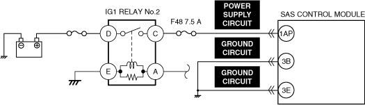
INSPECT SAS CONTROL MODULE POWER SUPPLY CIRCUIT FOR SHORT TO GROUND AND OPEN CIRCUIT
-
Warning
-
• Handling the component parts improperly can accidentally operate (deploy) the air bag module, which may seriously injure you. Read the service warnings/cautions and the workshop manual before handling the air bag system components.
• Disconnect the driver-side knee air bag module connector.
• Disconnect the driver-side air bag module connectors.
• Remove the clock spring.
• Disconnect the passenger-side air bag module connector.
• Disconnect the driver and passenger-side side air bag module for front passenger connectors.
• Disconnect the driver and passenger-side front seat connectors.
• Disconnect the driver and passenger-side curtain air bag module connectors.
• Disconnect the driver and passenger-side front pre-tensioner seat belt connectors.
• Disconnect the driver and passenger-side rear pre-tensioner seat belt connectors.
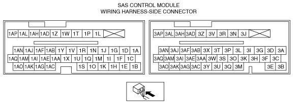
• Disconnect the all SAS control module connectors.
• Connect the negative battery terminal.
• Inspect the power supply circuit for an open circuit and short to ground.
• Is the circuit normal?
|
Yes
|
Go to the next step.
|
|
No
|
Repair or replace the malfunctioning location and perform the repair completion verification.
|
|
6
|
INSPECT SAS CONTROL MODULE GROUND CIRCUIT
• Inspect the ground circuit for an open circuit.
• Is the circuit normal?
|
Yes
|
Perform the repair completion verification.
|
|
No
|
Repair or replace the malfunctioning location and perform the repair completion verification.
|
|
Repair completion verification
|
PERFORM SAS CONTROL MODULE DTC INSPECTION
• Connect the SAS control module connectors.
• Reconnect all disconnected connectors.
• Connect the negative battery terminal.
• Switch the ignition ON (engine off or on).
• Clear the DTC for the SAS control module using the M-MDS.
• Perform the DTC inspection for the SAS control module using the M-MDS.
• Are the same Pending DTCs present?
|
Yes
|
Refer to the controller area network (CAN) malfunction diagnosis flow to inspect for a CAN communication error.
If the CAN communication is normal, perform the diagnosis from Step 1.
• If the malfunction recurs, replace the SAS control module.
|
|
No
|
DTC troubleshooting completed.
|