• The OBD test inspects the integrity and function of the ABS and outputs the results when requested by the specific tests.
• On-board diagnostic test also:
• The OBD test is divided into 3 tests:
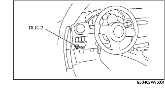
1. Connect the M-MDS to the vehicle DLC-2 connector.
2. After the vehicle is identified, select the following items from the initial screen of the M-MDS.
3. Verify the DTC according to the directions on the screen.
4. After completion of repairs, clear all DTCs stored in the ABS. (See Clearing DTCs Procedures.)
1. Connect the M-MDS to the vehicle DLC-2 connector.
2. After the vehicle is identified, select the following items from the initial screen of the M-MDS.
3. Verify the DTC according to the directions on the screen.
4. Press the clear button on the DTC screen to clear the DTC.
5. Verify that no DTCs are displayed.
1. Connect the M-MDS to the vehicle DLC-2 connector.
2. After the vehicle is identified, select the following items from the initial screen of the M-MDS.
3. Select the applicable PID from the PID table.
4. Verify the PID data according to the directions on the screen.
1. Connect the M-MDS to the vehicle DLC-2 connector.
2. After the vehicle is identified, select the following items from the initial screen of the M-MDS.
3. Select the active command modes from the PID table.
4. Perform the active command modes, inspect the operations for each parts.
|
DTC
|
System malfunction location
|
Page
|
|---|---|---|
|
M-MDS
|
||
|
B1317
|
Power supply system
|
(See DTC B1317, B1318 [ABS].)
|
|
B1318
|
Power supply system
|
(See DTC B1317, B1318 [ABS].)
|
|
B1342
|
ABS HU/CM system
|
(See DTC B1342 [ABS].)
|
|
B1484
|
Brake switch system
|
(See DTC B1484 [ABS].)
|
|
B2477
|
ABS HU/CM configuration
|
(See DTC B2477 [ABS].)
|
|
C1095
|
Pump motor, motor relay system
|
(See DTC C1095, C1096 [ABS].)
|
|
C1096
|
Pump motor, motor relay system
|
(See DTC C1095, C1096 [ABS].)
|
|
C1141
|
LF ABS sensor rotor system
|
|
|
C1142
|
RF ABS sensor rotor system
|
|
|
C1143
|
LR ABS sensor rotor system
|
|
|
C1144
|
RR ABS sensor rotor system
|
|
|
C1145
|
RF ABS wheel-speed sensor system
|
|
|
C1148
|
RF ABS wheel-speed sensor system
|
|
|
C1155
|
LF ABS wheel-speed sensor system
|
|
|
C1158
|
LF ABS wheel-speed sensor system
|
|
|
C1165
|
RR ABS wheel-speed sensor system
|
|
|
C1168
|
RR ABS wheel-speed sensor system
|
|
|
C1175
|
LR ABS wheel-speed sensor system
|
|
|
C1178
|
LR ABS wheel-speed sensor system
|
|
|
C1186
|
Fail-safe relay system
|
(See DTC C1186, C1266 [ABS].)
|
|
C1194
|
LF outlet solenoid valve system
|
|
|
C1198
|
LF inlet solenoid valve system
|
|
|
C1210
|
RF outlet solenoid valve system
|
|
|
C1214
|
RF inlet solenoid valve system
|
|
|
C1233
|
LF ABS wheel-speed sensor/ABS sensor rotor system
|
|
|
C1234
|
RF ABS wheel-speed sensor/ABS sensor rotor system
|
|
|
C1235
|
RR ABS wheel-speed sensor/ABS sensor rotor system
|
|
|
C1236
|
LR ABS wheel-speed sensor/ABS sensor rotor system
|
|
|
C1242
|
LR outlet solenoid valve system
|
|
|
C1246
|
RR outlet solenoid valve system
|
|
|
C1250
|
LR inlet solenoid valve system
|
|
|
C1254
|
RR inlet solenoid valve system
|
|
|
C1266
|
Fail-safe relay system
|
(See DTC C1186, C1266 [ABS].)
|
|
C1805
|
Incorrect ABS HU/CM installed
|
(See DTC C1805 [ABS].)
|
|
U0073
|
CAN system communication error
|
|
|
U1900
|
Communication error to other module
|
|
|
U2023
|
Abnormal message from PCM
|
|
PID name
(definition)
|
Unit/Condition
|
Operation condition (reference)
|
Action
|
ABS HU/CM terminal
|
|---|---|---|---|---|
|
ABS_VOLT
(System battery voltage value)
|
V
|
• Ignition switch at ON: Approx. 12.2 V
• Idling: Approx. 14.1 V
|
Inspect the power supply circuit.
(See ABS SYSTEM INSPECTION.)
|
J
|
|
ABSLF_I
(Left front inlet solenoid valve output state)
|
On/Off
|
• Solenoid valve activated: On
• Solenoid valve not activated: Off
|
Inspect the ABS HU/CM.
(See ABS HU/CM INSPECTION.)
|
-
|
|
ABSLF_O
(Left front outlet solenoid valve output state)
|
On/Off
|
• Solenoid valve activated: On
• Solenoid valve not activated: Off
|
Inspect the ABS HU/CM.
(See ABS HU/CM INSPECTION.)
|
-
|
|
ABSLR_I
(Left rear inlet solenoid valve output state)
|
On/Off
|
• Solenoid valve activated: On
• Solenoid valve not activated: Off
|
Inspect the ABS HU/CM.
(See ABS HU/CM INSPECTION.)
|
-
|
|
ABSLR_O
(Left rear outlet solenoid valve output state)
|
On/Off
|
• Solenoid valve activated: On
• Solenoid valve not activated: Off
|
Inspect the ABS HU/CM.
(See ABS HU/CM INSPECTION.)
|
-
|
|
ABSPMPRLY
(Motor relay output state)
|
On/Off
|
• Relay activated: On
• Relay not activated: Off
|
Inspect the ABS HU/CM.
(See ABS HU/CM INSPECTION.)
|
-
|
|
ABSRF_I
(Right front inlet solenoid valve output state)
|
On/Off
|
• Solenoid valve activated: On
• Solenoid valve not activated: Off
|
Inspect the ABS HU/CM.
(See ABS HU/CM INSPECTION.)
|
-
|
|
ABSRF_O
(Right front outlet solenoid valve output state)
|
On/Off
|
• Solenoid valve activated: On
• Solenoid valve not activated: Off
|
Inspect the ABS HU/CM.
(See ABS HU/CM INSPECTION.)
|
-
|
|
ABSRR_I
(Right rear inlet solenoid valve output state)
|
On/Off
|
• Solenoid valve activated: On
• Solenoid valve not activated: Off
|
Inspect the ABS HU/CM.
(See ABS HU/CM INSPECTION.)
|
-
|
|
ABSRR_O
(Right rear outlet solenoid valve output state)
|
On/Off
|
• Solenoid valve activated: On
• Solenoid valve not activated: Off
|
Inspect the ABS HU/CM.
(See ABS HU/CM INSPECTION.)
|
-
|
|
ABSVLVRLY
(Fail-safe relay output state)
|
On/Off
|
• Fail-safe relay is
activated: On
• Fail-safe relay is deactivated: Off
|
Inspect ABS HU/CM.
(See ABS HU/CM INSPECTION)
|
-
|
|
BOO_ABS
(Brake pedal switch input)
|
On/Off
|
• Brake pedal depressed: On
• Brake pedal released: Off
|
Inspect the brake switch.
|
N
|
|
CCNTABS
(Number of continuous codes)
|
-
|
• DTCs detected:
1-255
• No DTCs detected: 0
|
Perform the DTC inspection.
|
-
|
|
LF_WSPD
(Left front ABS wheel-speed sensor input)
|
KPH, MPH
|
• Vehicle stopped: 0 KPH, 0 MPH
• Vehicle running: Vehicle speed
|
Inspect the ABS wheel-speed sensor.
|
E, F
|
|
LR_WSPD
(Left rear ABS wheel-speed sensor input)
|
KPH, MPH
|
• Vehicle stopped: 0 KPH, 0 MPH
• Vehicle running: Vehicle speed
|
Inspect the ABS wheel-speed sensor.
|
G, H
|
|
PMP_MOTOR
(Pump motor output state)
|
On/Off
|
• Pump motor activated: On
• Pump motor not activated: Off
|
Inspect the ABS HU/CM.
(See ABS HU/CM INSPECTION.)
|
-
|
|
RF_WSPD
(Right front ABS wheel-speed sensor input)
|
KPH, MPH
|
• Vehicle stopped: 0 KPH, 0 MPH
• Vehicle running: Vehicle speed
|
Inspect the ABS wheel-speed sensor.
|
M, O
|
|
RR_WSPD
(Right rear ABS wheel-speed sensor input)
|
KPH, MPH
|
• Vehicle stopped: 0 KPH, 0 MPH
• Vehicle running: Vehicle speed
|
Inspect the ABS wheel-speed sensor.
|
I, L
|