Diagnostic procedure
|
STEP
|
INSPECTION
|
ACTION
|
|
|---|---|---|---|
|
1
|
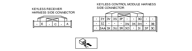
INSPECT WIRING HARNESS BETWEEN KEYLESS RECEIVER AND GROUND
• Disconnect keyless receiver connector.
• Is there continuity between keyless receiver terminal E and ground?
|
Yes
|
Go to next step.
|
|
No
|
• Repair the wiring harness between the keyless receiver and ground.
• Go to next step.
|
||
|
2
|
INSPECT COMMUNICATION CIRCUIT FOR CONTINUITY
• Disconnect keyless control module connector and keyless receiver connector.
• Inspect the continuity between the following connector terminals.
• Is there continuity?
|
Yes
|
Go to next step.
|
|
No
|
• Repair the wiring harness between the keyless receiver and keyless control module.
• Go to next step.
|
||
|
3
|
INSPECT KEYLESS RECEIVER POWER SUPPLY CIRCUIT
• Turn ignition switch to ON position.
• Measure voltage at terminal 3S of keyless control module connector.
• Is voltage more than 7.5 V?
|
Yes
|
Replace keyless receiver.
|
|
No
|
Replace the keyless control module and perform the resetting procedure for the advanced keyless system when replacing the keyless control module.
(See IMMOBILIZER SYSTEM COMPONENT REPLACEMENT/KEY ADDITION AND CLEARING [WITH ADVANCED KEYLESS SYSTEM])
|
||