Engine coolant temperature: 0—45 °C {32—113 °F}, 60 °C {140 °F} or more
ac5uuw00006346
|
DTC P0171:00 [PCM (SKYACTIV-G 1.5, SKYACTIV-G 2.0)]
id0102i6934200
Details On DTCs
|
DESCRIPTION |
Fuel trim system too lean |
|
|---|---|---|
|
DETECTION CONDITION
|
Determination conditions
|
• Any one of the following conditions is met:
|
|
Preconditions
|
• Engine coolant temperature: 0—45 °C {32—113 °F}, 60 °C {140 °F} or more*1
*1: Standard can be verified by displaying PIDs using M-MDS
|
|
|
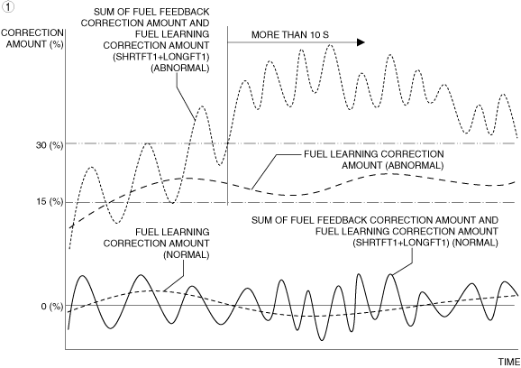
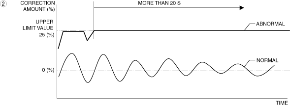
Malfunction determination period
|
• 10 s or 20 s period
|
|
|
Drive cycle
|
• 2
|
|
|
Self test type
|
• CMDTC self test
|
|
|
Sensor used
|
• A/F sensor
|
|
|
FAIL-SAFE FUNCTION
|
• Not applicable
|
|
|
VEHICLE STATUS WHEN DTCs ARE OUTPUT
|
• Illuminates check engine light.
|
|
|
POSSIBLE CAUSE
|
• Erratic signal to PCM
• High-pressure side fuel delivery system malfunction
• Fuel leakage in fuel line
• Low-pressure side fuel delivery system malfunction
• Fuel injector malfunction
• Improper operation of purge control system
• PCV valve malfunction
• MAF sensor malfunction
• Air cleaner element malfunction
• MAP sensor malfunction
• Air suction in intake air system
• Improper operation of electric variable valve timing control system
• Improper operation of hydraulic variable valve timing control system
• A/F sensor malfunction
• Poor fuel quality
• PCM malfunction
|
|
System Wiring Diagram
Function Explanation (DTC Detection Outline)
ac5uuw00006346
|
ac5uuw00006347
|
Repeatability Verification Procedure
PID Item/Simulation Item Used In Diagnosis
PID/DATA monitor item table
|
Item |
Definition |
Unit |
Condition/Specification |
|---|---|---|---|
|
APP
|
Accelerator pedal opening angle (relative value) with the fully released status as 0% and fully depressed status as 100%
|
%
|
• Accelerator pedal released: Approx. 0%
• Accelerator pedal fully depressed: Approx. 100%
|
|
ECT
|
Engine coolant temperature input from ECT sensor
|
°C, °F
|
• Displays ECT
|
|
ECT sensor voltage
|
V
|
Ignition switched ON (engine off)
• ECT is 92 °C {198 °F}: Approx. 0.65 V
Idle (after warm up)
• ECT is 93 °C {199 °F}: Approx. 0.64 V
Racing (Engine speed is 2,000 rpm)
• ECT is 92 °C {198 °F}: Approx. 0.66 V
Racing (Engine speed is 4,000 rpm)
• ECT is 93 °C {199 °F}: Approx. 0.64 V
|
|
|
EVAPCP
|
Purge solenoid valve control duty value
|
%
|
• Idle (after warm up): 0% (ECT is 59 °C {140 °F} or less)
• Racing (Engine speed 2,000 rpm): 0% (ECT is 94 °C {201 °F})
• Racing (Engine speed 4,000 rpm): Approx. 10.1% (ECT is 94 °C {201 °F})
|
|
FP
|
Fuel pump operation status
|
Off/On
|
• Ignition switched ON (engine off): Off
• Cranking: On
• Idle (after warm up): On
|
|
FUEL_PRES
|
Fuel pressure (absolute) input from fuel pressure sensor
|
KPa {MPa}, mBar {Bar}, psi, in H20
|
• Displays fuel pressure (absolute)
|
|
Fuel pressure sensor voltage
|
V
|
Idle (ECT 80 °C {176 °F})
• Fuel pressure is 10 MPa {102 kgf/cm2, 1450 psi}: Approx. 1.4 V
|
|
|
IAT2
|
Intake air temperature (No.2) input from IAT sensor No.2
|
°C, °F
|
• Displays IAT (No.2)
|
|
IAT sensor No.2 voltage
|
V
|
• IAT2 is 20 °C {68 °F}: Approx. 3.57 V
• IAT2 is 40 °C {104 °F}: Approx. 2.70 V
• IAT2 is 60 °C {140 °F}: Approx. 1.87 V
|
|
|
MAF
|
Mass air flow input from MAF sensor
|
g/Sec
|
• Displays MAF
|
|
MAF sensor voltage
|
V
|
• Ignition switched ON (engine off) (MAF: 0.00 g/s {0 lb/min}): Approx. 1.69 V (ECT is 53 °C {127 °F})
• Idle (after warm up) (MAF: 2.50 g/s {0.331 lb/min}): Approx. 1.89 V (ECT is 93 °C {199 °F})
• Racing (engine speed is 2,000 rpm) (MAF: 3.80 g/s {0.503 lb/min}): Approx. 2.02 V (ECT is 95 °C {203 °F})
|
|
|
MAP
|
Manifold absolute pressure input from MAP sensor
|
KPa {MPa}, mBar {Bar}, psi, in H20
|
• Displays MAP
|
|
MAP_V
|
MAP sensor voltage
|
V
|
• Ignition switched ON (engine off) (MAP:101 kPa {1.03 kgf/cm2, 14.6 psi}): Approx. 4.12 V
• Idle (after warm up) (MAP: 33 kPa {0.34 kgf/cm2, 4.8 psi}): Approx. 1.9 V
• Racing (engine speed is 2,000 rpm) (MAP: 26 kPa {0.27 kgf/cm2, 3.8 psi}): Approx. 1.23 V
|
|
O2S11
|
A/F sensor current
|
µA
|
• Idle (after warm up): −59 µA (ECT is 92 °C {198 °F})
• Deceleration fuel cut (accelerator pedal released from engine speed of 4,000 rpm or more): Approx. 3.48 mA (ECT is 92 °C {198 °F})
|
|
TP_REL
|
Throttle valve opening angle (relative value) with value at throttle valve fully close timing as the start point
|
%
|
• Accelerator pedal released: Approx. 12.15%
• Accelerator pedal fully depressed: Approx. 81.96%
|
|
VT_EX_ACT
|
Actual exhaust variable valve timing control
• Retard amount from max advance position
|
°(deg)
|
• Displays actual exhaust variable valve timing—retard amount from max advance position
Ignition switched ON (engine off)
Idle (after warm up)
Racing (engine speed is 2,000 rpm)
Racing (engine speed is 4,000 rpm)
|
|
VT_EX_DES
|
Target exhaust variable valve timing control
• Retard amount from max advance position
|
°(deg)
|
• Displays target exhaust variable valve timing—retard amount from max advance position
Ignition switched ON (engine off)
Idle (after warm up)
Racing (engine speed is 2,000 rpm)
Racing (engine speed is 4,000 rpm)
|
|
VT_IN_ACT
|
Actual intake variable valve timing control
• Advance amount from max retard position
|
°(deg)
|
• Displays actual intake variable valve timing—advance amount from max retard position
Ignition switched ON (engine off)
Idle (after warm up)
Racing (engine speed is 2,000 rpm)
Racing (engine speed is 4,000 rpm)
|
|
VT_IN_DES
|
Target intake variable valve timing control
• Advance amount from max retard position
|
°(deg)
|
• Displays target intake variable valve timing—advance amount from max retard position
Ignition switched ON (engine off)
Idle (after warm up)
Racing (engine speed is 2,000 rpm)
Racing (engine speed is 4,000 rpm)
|
Simulation item table
|
Item |
Applicable component |
Operation |
Operation condition |
|
|---|---|---|---|---|
|
Engine condition |
Other condition |
|||
|
FP
|
Fuel pump
|
Select OFF/ON to forcibly drive/stop the fuel pump.
|
• Under the following conditions:
|
Not applicable
|
|
INJ_1
|
Fuel injector No.1
|
Select OFF to forcibly stop the fuel injector No.1.
|
• Under the following conditions:
|
|
|
INJ_2
|
Fuel injector No.2
|
Select OFF to forcibly stop the fuel injector No.2.
|
||
|
INJ_3
|
Fuel injector No.3
|
Select OFF to forcibly stop the fuel injector No.3.
|
||
|
INJ_4
|
Fuel injector No.4
|
Select OFF to forcibly stop the fuel injector No.4.
|
||
Function Inspection Using M-MDS
|
STEP |
INSPECTION |
RESULTS |
ACTION |
|---|---|---|---|
|
1
|
PURPOSE: VERIFY RELATED SERVICE INFORMATION AVAILABILITY
• Verify related Service Information availability.
• Is any related Service Information available?
|
Yes
|
Perform repair or diagnosis according to the available Service Information.
• If the vehicle is not repaired, go to the next step.
|
|
No
|
Go to the next step.
|
||
|
2
|
PURPOSE: IDENTIFY TRIGGER DTC FOR FREEZE FRAME DATA
• Is the DTC P0171:00 on FREEZE FRAME DATA?
|
Yes
|
Go to the next step.
|
|
No
|
Go to the troubleshooting procedure for DTC on FREEZE FRAME DATA.
|
||
|
3
|
PURPOSE: RECORD VEHICLE STATUS AT TIME OF DTC DETECTION TO UTILIZE WITH REPEATABILITY VERIFICATION
• Record the FREEZE FRAME DATA/snapshot data on the repair order.
|
—
|
Go to the next step.
|
|
4
|
PURPOSE: VERIFY IF INPUT SIGNAL TO PCM AFFECTS FUEL INJECTION
• Start the engine.
• Access the following PIDs using the M-MDS:
• Is there any signal that is far out of specification?
|
Yes
|
Inspect the suspected sensor and related wiring harness.
• If there is any malfunction:
• If there is no malfunction:
|
|
No
|
Go to the next step.
|
||
|
5
|
PURPOSE: VERIFY CONNECTOR CONNECTIONS
• Start the engine.
• Access the following PIDs using the M-MDS:
• When the following parts are shaken, does the PID value include a PID item which has changed?
|
Yes
|
Repair or replace the applicable connector parts.
Go to Troubleshooting Diagnostic Procedure to perform the procedure from Step 19.
|
|
No
|
Go to the next step.
|
||
|
6
|
PURPOSE: VERIFY FUEL PRESSURE (HIGH-SIDE) MALFUNCTION
• Switch the ignition off.
• Reconnect all disconnected connectors.
• Start the engine and idle it.
• Access the FUEL_PRES PID using the M-MDS.
• Is the FUEL_PRES PID value approx. 10 MPa {102 kgf/cm2, 1450 psi}?
|
Yes
|
Go to the next step.
|
|
No
|
FUEL_PRES PID value is lower than 10 MPa {102 kgf/cm2, 1450 psi}:
• Go to Troubleshooting Diagnostic Procedure to perform the procedure from Step 1.
FUEL_PRES PID value is higher than 10 MPa {102 kgf/cm2, 1450 psi}:
• Go to Step 8.
|
||
|
7
|
PURPOSE: VERIFY FUEL PRESSURE (LOW-SIDE) MALFUNCTION
• Bleed the remaining pressure in the fuel line using the following procedure.
• Switch the ignition off.
• Install the fuel pump relay.
• Switch the ignition ON (engine off).
• Display PID FUEL_PRES and simulation item FP using the M-MDS.
• Turn simulation item FP on.
• Is the FUEL_PRES PID value 425—505 kPa {4.34—5.14 kgf/cm2, 61.7—73.2 psi}?
|
Yes
|
Go to the next step.
|
|
No
|
Go to Troubleshooting Diagnostic Procedure to perform the procedure from Step 5.
|
||
|
8
|
PURPOSE: VERIFY IF MALFUNCTION CAUSED BY FUEL INJECTOR IMPROPER OPERATION
• Switch the ignition off.
• Reconnect all disconnected connectors.
• Start the engine and idle it.
• Access the following simulation items using the M-MDS:
• Turn each fuel injector from on to off using the simulation items.
• Does the vibration during idling worsen?
|
Yes
|
Go to the next step.
|
|
No
|
Go to Troubleshooting Diagnostic Procedure to perform the procedure from Step 6.
|
||
|
9
|
PURPOSE: VERIFY IF MALFUNCTION CAUSED BY PURGE SOLENOID VALVE IMPROPER OPERATION
• Start the engine and idle it.
• Access the EVAPCP PID using the M-MDS.
• Is the EVAPCP PID value normal?
|
Yes
|
Go to the next step.
|
|
No
|
Go to Troubleshooting Diagnostic Procedure to perform the procedure from Step 7.
|
||
|
10
|
PURPOSE: VERIFY MAF SENSOR
• Start the engine and idle it.
• Access the MAF PID using the M-MDS.
• Is the MAF PID value normal?
|
Yes
|
Go to the next step.
|
|
No
|
Go to Troubleshooting Diagnostic Procedure to perform the procedure from Step 9.
|
||
|
11
|
PURPOSE: VERIFY MAP SENSOR
• Start the engine and idle it.
• Access the following PIDs using the M-MDS:
• Are all items normal?
|
Yes
|
Go to the next step.
|
|
No
|
Go to Troubleshooting Diagnostic Procedure to perform the procedure from Step 11.
|
||
|
12
|
PURPOSE: VERIFY INTAKE VALVE TIMING
• Start the engine and idle it.
• Access the following PIDs using the M-MDS:
• Depress the accelerator pedal to increase the engine speed.
• Does the monitor value of the PID item VT_IN_ACT conform to the VT_IN_DES PID value?
|
Yes
|
Go to the next step.
|
|
No
|
Go to Troubleshooting Diagnostic Procedure to perform the procedure from Step 13.
|
||
|
13
|
PURPOSE: VERIFY EXHAUST VALVE TIMING
• Start the engine and idle it.
• Access the following PIDs using the M-MDS:
• Perform the following:
• Does the monitor value of the PID item VT_EX_ACT conform to the VT_EX_DES PID value?
|
Yes
|
Go to the next step.
|
|
No
|
Go to Troubleshooting Diagnostic Procedure to perform the procedure from Step 16.
|
||
|
14
|
PURPOSE: VERIFY A/F SENSOR
• Access the O2S11 PID using the M-MDS.
• Is the O2S11 PID value normal?
|
Yes
|
Go to the next step.
|
|
No
|
Go to Troubleshooting Diagnostic Procedure to perform the procedure from Step 17.
|
||
|
15
|
PURPOSE: VERIFY DTC
• Switch the ignition off, then ON (engine off).
• Retrieve the PCM DTCs using the M-MDS.
• Are any DTCs present?
|
Yes
|
Go to the applicable DTC inspection.
Go to Troubleshooting Diagnostic Procedure to perform the procedure from Step 1.
|
|
No
|
Go to Troubleshooting Diagnostic Procedure to perform the procedure from Step 1.
|
Troubleshooting Diagnostic Procedure
|
STEP |
INSPECTION |
RESULTS |
ACTION |
|---|---|---|---|
|
1
|
PURPOSE: VERIFY IF CAUSE OF MALFUNCTION IS RELATED TO LACK OF FUEL
• Verify the remaining amount of fuel.
• Is there a lack of fuel?
|
Yes
|
Refill the fuel, then go to Step 19.
|
|
No
|
Go to the next step.
|
||
|
2
|
PURPOSE: DETERMINE INTEGRITY OF FUEL PRESSURE SENSOR
• Inspect the fuel pressure sensor.
• Is there any malfunction?
|
Yes
|
Replace the fuel distributor, then go to Step 19.
|
|
No
|
Go to the next step.
|
||
|
3
|
PURPOSE: DETERMINE INTEGRITY OF HIGH PRESSURE FUEL PUMP
• Inspect the high pressure fuel pump.
• Is there any malfunction?
|
Yes
|
Replace the high pressure fuel pump, then go to Step 19.
|
|
No
|
Go to the next step.
|
||
|
4
|
PURPOSE: VERIFY IF MALFUNCTION RELATED TO FUEL LEAK FROM FUEL SYSTEM OR RESTRICTION AFFECTS DIAGNOSTIC RESULTS
• Inspect the fuel system pipes (low to high pressure sides) for fuel leakage and restriction.
• Is there any malfunction?
|
Yes
|
Repair or replace the malfunctioning part according to the inspection results, then go to Step 19.
|
|
No
|
Go to the next step.
|
||
|
5
|
PURPOSE: DETERMINE INTEGRITY OF FUEL PUMP UNIT
• Inspect the fuel pump unit.
• Is there any malfunction?
|
Yes
|
Replace the fuel pump unit, then go to Step 19.
|
|
No
|
Go to the next step.
|
||
|
6
|
PURPOSE: DETERMINE INTEGRITY OF FUEL INJECTOR
• Inspect the fuel injector.
• Is there any malfunction?
|
Yes
|
Replace the fuel injector, then go to Step 19.
|
|
No
|
Go to the next step.
|
||
|
7
|
PURPOSE: DETERMINE INTEGRITY OF PURGE SOLENOID VALVE
• Inspect the purge solenoid valve.
• Is there any malfunction?
|
Yes
|
Replace the purge solenoid valve, then go to Step 19.
|
|
No
|
Go to the next step.
|
||
|
8
|
PURPOSE: DETERMINE INTEGRITY OF PCV VALVE
• Inspect the PCV valve.
• Is there any malfunction?
|
Yes
|
Replace the PCV valve, then go to Step 19.
|
|
No
|
Go to the next step.
|
||
|
9
|
PURPOSE: DETERMINE INTEGRITY OF MAF SENSOR
• Inspect the MAF sensor.
• Is there any malfunction?
|
Yes
|
Replace the MAF sensor/IAT sensor No.1, then go to Step 19.
|
|
No
|
Go to the next step.
|
||
|
10
|
PURPOSE: VERIFY IF MALFUNCTION RELATED TO AIR CLEANER ELEMENT AFFECTS MEASUREMENT OF INTAKE AIR AMOUNT
• Inspect the air cleaner element.
• Is there any malfunction?
|
Yes
|
Replace the air cleaner element, then go to Step 19.
|
|
No
|
Go to the next step.
|
||
|
11
|
PURPOSE: DETERMINE INTEGRITY OF MAP SENSOR
• Reconnect all disconnected connectors.
• Inspect the MAP sensor.
• Is there any malfunction?
|
Yes
|
Replace the MAP sensor/IAT sensor No.2, then go to Step 19.
|
|
No
|
Go to the next step.
|
||
|
12
|
PURPOSE: VERIFY IF MALFUNCTION RELATED TO INTAKE AIR SYSTEM AFFECTS DIAGNOSTIC RESULTS
• Visually inspect for loose, cracked or damaged hoses on intake air system.
• Is there any malfunction?
|
Yes
|
Repair or replace the malfunctioning part according to the inspection results, then go to Step 19.
|
|
No
|
Go to the next step.
|
||
|
13
|
PURPOSE: DETERMINE INTEGRITY OF ELECTRIC VARIABLE VALVE TIMING DRIVER
• Inspect the electric variable valve timing driver.
• Is there any malfunction?
|
Yes
|
Replace the electric variable valve timing motor/driver, then go to Step 19.
|
|
No
|
Go to the next step.
|
||
|
14
|
PURPOSE: DETERMINE INTEGRITY OF ELECTRIC VARIABLE VALVE TIMING MOTOR
• Inspect the electric variable valve timing motor.
• Is there any malfunction?
|
Yes
|
Replace the electric variable valve timing motor/driver, then go to Step 19.
|
|
No
|
Go to the next step.
|
||
|
15
|
PURPOSE: DETERMINE INTEGRITY OF ELECTRIC VARIABLE VALVE TIMING ACTUATOR
• Inspect the electric variable valve timing actuator.
• Is there any malfunction?
|
Yes
|
Replace the electric variable valve timing actuator, then go to Step 19.
|
|
No
|
Go to the next step.
|
||
|
16
|
PURPOSE: DETERMINE INTEGRITY OF OCV
• Inspect the OCV.
• Is there any malfunction?
|
Yes
|
Replace the OCV, then go to Step 19.
|
|
No
|
Go to the next step.
|
||
|
17
|
PURPOSE: DETERMINE INTEGRITY OF A/F SENSOR
• Inspect the A/F sensor.
• Is there any malfunction?
|
Yes
|
Replace the A/F sensor, then go to Step 19.
|
|
No
|
Go to the next step.
|
||
|
18
|
PURPOSE: VERIFY IF MALFUNCTION RELATED TO EMISSION SYSTEM AFFECTS HO2S SIGNAL
• Verify the exhaust gas leakage from the exhaust system. (between A/F sensor and HO2S)
• Is there any malfunction?
|
Yes
|
Repair or replace the malfunctioning part according to the inspection results, then go to the next step.
|
|
No
|
Go to the next step.
|
||
|
19
|
PURPOSE: VERIFICATION OF VEHICLE REPAIR COMPLETION
• Always reconnect all disconnected connectors.
• Clear the DTC from the PCM memory using the M-MDS.
• Implement the repeatability verification procedure.
• Perform the Pending Trouble Code Access Procedure.
• Is the same Pending DTC present?
|
Yes
|
Repeat the inspection from Step 1.
• If the malfunction recurs, replace the PCM.
|
|
No
|
DTC troubleshooting completed.
|