FUEL PUMP UNIT REMOVAL/INSTALLATION [SKYACTIV-G 1.5, SKYACTIV-G 2.0]
id0114zg800900
-
Warning
-
• Highly pressurized fuel may spray out if the fuel line is cut. Due to the following dangers occurring with a fuel spray, always complete the “Fuel Line Safety Procedure” to prevent the fuel from spraying.
-
― Fuel may cause irritation if it comes in contact with skin and eyes.
― If fuel ignites and causes a fire, it may lead to serious injury or death, and damage to property and facilities.
• A person charged with static electricity could cause a fire or explosion, resulting in death or serious injury. Before draining fuel, make sure to discharge static electricity by touching the vehicle body.
-
Caution
-
• Disconnecting/connecting the quick release connector without cleaning it may cause damage to the fuel pipe and quick release connector. Always clean the quick release connector joint area before disconnecting/connecting using a cloth or soft brush, and make sure that it is free of foreign material.
1. Complete the “BEFORE SERVICE PRECAUTION”. (See BEFORE SERVICE PRECAUTION [SKYACTIV-G 1.5, SKYACTIV-G 2.0].)
2. If the fuel gauge level indicates 15/16 or more, refer to the “FUEL DRAINING PROCEDURE” and drain the fuel. (See FUEL DRAINING PROCEDURE [SKYACTIV-G 1.5, SKYACTIV-G 2.0].)
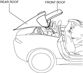
3. Using the retractable hardtop switch, keep the retractable hardtop half-open. (with retractable hardtop)
4. Disconnect the negative battery terminal. (See NEGATIVE BATTERY TERMINAL DISCONNECTION/CONNECTION.)
5. Remove the following parts:
- (1) Seat (LH) (See SEAT REMOVAL/INSTALLATION.)
-
- (2) Selector lever knob (AT) (See AUTOMATIC TRANSMISSION SHIFT MECHANISM REMOVAL/INSTALLATION.)
-
- (3) Shift lever knob (MT) (See TRANSMISSION REMOVAL/INSTALLATION [M66M-D].)
-
- (4) Shift panel compartment (See SHIFT PANEL REMOVAL/INSTALLATION.)
-
- (5) Upper panel (See UPPER PANEL REMOVAL/INSTALLATION.)
-
- (6) Parking brake lever boot panel (See PARKING BRAKE LEVER BOOT PANEL REMOVAL/INSTALLATION.)
-
- (7) Rear console (See REAR CONSOLE REMOVAL/INSTALLATION.)
-
- (8) Scuff plate (See SCUFF PLATE REMOVAL/INSTALLATION.)
-
- (9) Tire house trim (See TIRE HOUSE TRIM REMOVAL/INSTALLATION.)
-
- (10) Seat back bar garnish (See SEAT BACK BAR GARNISH REMOVAL/INSTALLATION.)
-
- (11) Quarter trim (See QUARTER TRIM REMOVAL/INSTALLATION.)
-
- (12) Wind blocker (See WIND BLOCKER REMOVAL/INSTALLATION.)
-
- (13) Roof hook lever (See ROOF HOOK REMOVAL/INSTALLATION.)
-
- (14) Back trim (See BACK TRIM REMOVAL/INSTALLATION.)
-
- (15) retractable hardtop control module (with retractable hardtop) (See RETRACTABLE HARDTOP CONTROL MODULE REMOVAL/INSTALLATION)
-
- (16) CD player, CD player bracket (with CD player) (See CD PLAYER REMOVAL/INSTALLATION.)
-
- (17) DVD/CD player, DVD/CD player bracket (with DVD/CD player) (See DVD/CD PLAYER REMOVAL/INSTALLATION.)
-
- (18) Side shelf (LH) (See SIDE SHELF REMOVAL/INSTALLATION.)
-
- (19) Rear package trim (See REAR PACKAGE TRIM REMOVAL/INSTALLATION.)
-
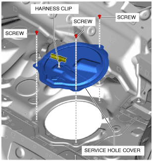
6. Remove the service hole cover.
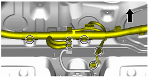
7. Disconnect the connector and harness as shown in the figure.
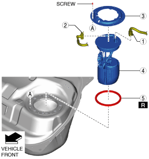
8. Remove in the order indicated in the table.
|
1
|
Fuel pump unit connector
|
|
2
|
Quick release connector
|
|
3
|
Set plate
|
|
4
|
Fuel pump unit
|
|
5
|
Packing
|
9. Install in the reverse order of removal.
10. Complete the “AFTER SERVICE PRECAUTION”. (See AFTER SERVICE PRECAUTION [SKYACTIV-G 1.5, SKYACTIV-G 2.0].)