 |
amxzzw00004460
AUTOMATIC TRANSMISSION REMOVAL/INSTALLATION [SJ6A-EL]
id051311249200
Removal
1. Disconnect the negative battery terminal. (See NEGATIVE BATTERY TERMINAL DISCONNECTION/CONNECTION.)
2. Remove the selector lever knob. (See AUTOMATIC TRANSMISSION SHIFT MECHANISM REMOVAL/INSTALLATION.)
3. Remove the shift panel component. (See SHIFT PANEL REMOVAL/INSTALLATION.)
4. Remove the upper panel. (See UPPER PANEL REMOVAL/INSTALLATION.)
5. Remove the parking brake lever boot panel. (See PARKING BRAKE LEVER BOOT PANEL REMOVAL/INSTALLATION.)
6. Remove the rear console. (See REAR CONSOLE REMOVAL/INSTALLATION.)
7. Remove the front console panel. (See FRONT CONSOLE PANEL REMOVAL/INSTALLATION.)
8. Remove the front console component. (See FRONT CONSOLE REMOVAL/INSTALLATION.)
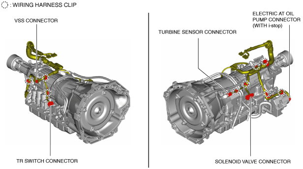
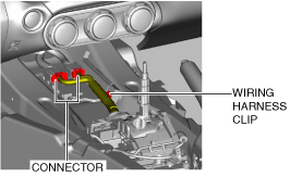
9. Disconnect the connector and wiring harness clip.
amxzzw00004460
|
10. Place a clean rag behind the engine so that the engine does not contact the rear housing when it is tilted.
amxzzw00005238
|
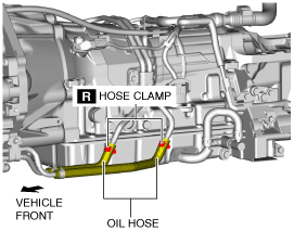
11. Drain the ATF. (See AUTOMATIC TRANSMISSION FLUID (ATF) REPLACEMENT [SJ6A-EL].)
12. Disconnect the oil hose.
amxzzw00003320
|
13. Remove the front crossmember under cover. (See FRONT CROSSMEMBER UNDER COVER REMOVAL/INSTALLATION.)
14. Disconnect the control rod from the selector lever component. (See AUTOMATIC TRANSMISSION SHIFT MECHANISM REMOVAL/INSTALLATION.)
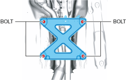
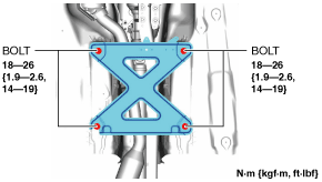
15. Remove the tunnel member.
amxuuw00003817
|
16. Disconnect the HO2S connector. (See HEATED OXYGEN SENSOR (HO2S) REMOVAL/INSTALLATION [SKYACTIV-G 1.5, SKYACTIV-G 2.0].)
17. Remove the exhaust manifold (WU-TWC). (See EXHAUST SYSTEM REMOVAL/INSTALLATION [SKYACTIV-G 1.5, SKYACTIV-G 2.0].)
18. Temporarily install the engine mount. (See ENGINE MOUNT DISASSEMBLY/ASSEMBLY [SKYACTIV-G 1.5, SKYACTIV-G 2.0].)
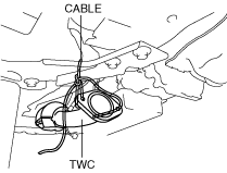
19. Suspend the TWC using a cable as shown in the figure.
amxuuw00002847
|
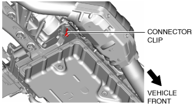
20. Disconnect the connector clip.
amxzzw00003321
|
21. Remove the starter. (See STARTER REMOVAL/INSTALLATION [SKYACTIV-G 1.5, SKYACTIV-G 2.0].)
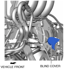
22. Remove the blind cover.
amxzzw00005239
|
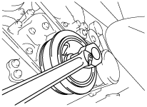
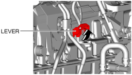
23. Hold the crankshaft pulley to prevent torque converter from rotating.
ardjjw00004581
|
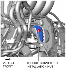
24. Remove the torque converter installation nuts from the starter installation hole.
amxzzw00005240
|
25. Remove the power plant frame. (See POWER PLANT FRAME REMOVAL [M66M-D].)
26. Remove the propeller shaft. (See PROPELLER SHAFT REMOVAL/INSTALLATION.)
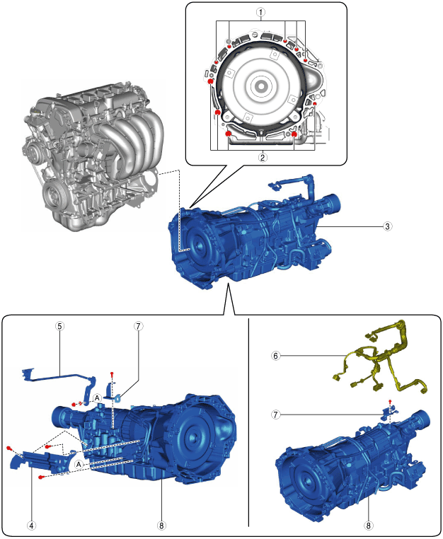
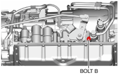
27. Remove in the order indicated in the table.
amxzzw00005241
|
|
1
|
Transmission mounting bolts (upper side)
|
|
2
|
Transmission mounting bolts (lower side)
|
|
3
|
Transmission component
|
|
4
|
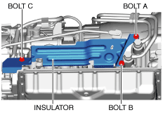
Insulator
|
|
5
|
Control rod
|
|
6
|
Short cord
(See Short cord removal note.)
|
|
7
|
Bracket
|
|
8
|
Transmission
|
Transmission mounting bolt (lower side) removal note
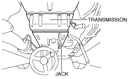
1. Support the transmission on a jack.
amxuuw00003505
|
2. Remove the transmission mounting bolts (lower side).
3. Remove the transmission component.
Short cord removal note
1. Disconnect the connector and the wiring harness clip.
amxzzw00003322
|
2. Remove the short cord.
Installation
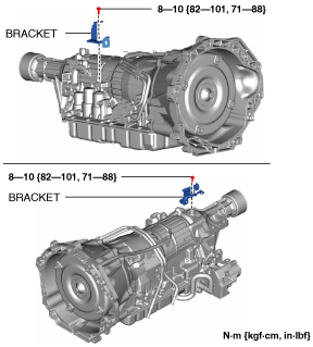
1. Install the bracket.
amxzzw00003323
|
2. Connect the connector and the wiring harness clips, and install the short cord.
amxzzw00003322
|
amxuuw00003508
|
3. Install the control rod to the transmission. (See AUTOMATIC TRANSMISSION SHIFT MECHANISM REMOVAL/INSTALLATION.)
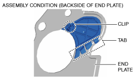
4. Install the insulator using the following procedures.
amxuuw00002860
|
amxuuw00002861
|
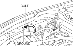
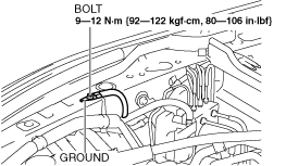
5. Remove the ground.
amxzzw00005242
|
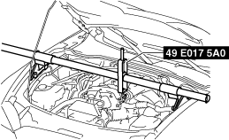
6. Set the SST (49 E017 5A0) as shown in the figure.
amxzzw00005243
|
7. Using the SST (49 E017 5A0), lower the rear side of the engine while being careful not to allow parts on the back of the engine to contact the vehicle body.
8. Support the transmission on a jack.
amxuuw00003505
|
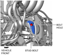
9. Verify that the torque converter stud bolts are inserted into the drive plate bolt holes from the starter installation hole.
amxzzw00005244
|
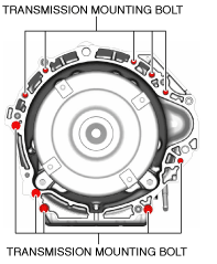
10. Install the transmission mounting bolts.
amxuuw00003510
|
11. Install the propeller shaft. (See PROPELLER SHAFT REMOVAL/INSTALLATION.)
12. Install the power plant frame. (See POWER PLANT FRAME INSTALLATION [M66M-D].)
13. Remove the tunnel member temporarily.
amxuuw00003817
|
14. Hold the crankshaft pulley to prevent torque converter from rotating.
ardjjw00004581
|
15. Tighten the torque converter installation nuts.
amxzzw00005240
|
16. Install the blind cover.
amxzzw00005239
|
amxuuw00003512
|
17. Install the starter. (See STARTER REMOVAL/INSTALLATION [SKYACTIV-G 1.5, SKYACTIV-G 2.0].)
18. Connect the connector clip.
amxzzw00003321
|
19. Install the TWC to the exhaust manifold (WU-TWC). (See EXHAUST SYSTEM REMOVAL/INSTALLATION [SKYACTIV-G 1.5, SKYACTIV-G 2.0].)
20. Connect the HO2S connector. (See HEATED OXYGEN SENSOR (HO2S) REMOVAL/INSTALLATION [SKYACTIV-G 1.5, SKYACTIV-G 2.0].)
21. Install the tunnel member.
amxuuw00003818
|
22. Connect the control rod from the selector lever component. (See AUTOMATIC TRANSMISSION SHIFT MECHANISM REMOVAL/INSTALLATION.)
23. Install the front crossmember under cover. (See FRONT CROSSMEMBER UNDER COVER REMOVAL/INSTALLATION.)
24. Remove the SST (49 E017 5A0).
25. Install the ground.
amxzzw00005245
|
26. Connect the oil hose.
amxzzw00003320
|
27. Connect the connector and the wiring harness clip.
amxzzw00004460
|
28. Install the front console component. (See FRONT CONSOLE REMOVAL/INSTALLATION.)
29. Install the front console panel. (See FRONT CONSOLE PANEL REMOVAL/INSTALLATION.)
30. Install the rear console. (See REAR CONSOLE REMOVAL/INSTALLATION.)
31. Install the parking brake lever boot panel. (See PARKING BRAKE LEVER BOOT PANEL REMOVAL/INSTALLATION.)
32. Install the upper panel. (See UPPER PANEL REMOVAL/INSTALLATION.)
33. Install the shift panel component. (See SHIFT PANEL REMOVAL/INSTALLATION.)
34. Install the selector lever knob. (See AUTOMATIC TRANSMISSION SHIFT MECHANISM REMOVAL/INSTALLATION.)
35. Connect the negative battery terminal. (See NEGATIVE BATTERY TERMINAL DISCONNECTION/CONNECTION.)
36. Add the ATF. (See AUTOMATIC TRANSMISSION FLUID (ATF) REPLACEMENT [SJ6A-EL].)
37. Inspect selector lever operation. (See SELECTOR LEVER INSPECTION.)
38. Inspect for leakage of ATF from all connecting points.
39. Perform the mechanical system test. (See MECHANICAL SYSTEM TEST [SJ6A-EL].)
40. Perform the road test. (See ROAD TEST [SJ6A-EL].)
41. Perform the “Initial Learning” (automatic transmission replacement). (See INITIAL LEARNING PROCEDURE [SJ6A-EL].)