 |
amxuuw00003524
TRANSMISSION RANGE (TR) SWITCH INSPECTION [SJ6A-EL]
id051311251300
Operating Inspection
1. Verify that the engine starts only when the selector lever is in the P position or N position with the brake pedal depressed and that the engine does not start with the selector lever in other positions.
2. Verify that the back-up lights turn on and the R position warning alarm sound is activated only when the selector lever is in the R position. In addition, verify that they do not operate in other positions.
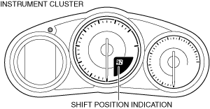
3. Shift the selector lever and verify that the shift position indication and selector lever position match.
amxuuw00003524
|
Continuity Inspection
1. Disconnect the negative battery terminal. (See NEGATIVE BATTERY TERMINAL DISCONNECTION/CONNECTION.)
2. Remove the selector lever knob. (See AUTOMATIC TRANSMISSION SHIFT MECHANISM REMOVAL/INSTALLATION.)
3. Remove the shift panel component. (See SHIFT PANEL REMOVAL/INSTALLATION.)
4. Remove the upper panel. (See UPPER PANEL REMOVAL/INSTALLATION.)
5. Remove the parking brake lever boot panel. (See PARKING BRAKE LEVER BOOT PANEL REMOVAL/INSTALLATION.)
6. Remove the rear console. (See REAR CONSOLE REMOVAL/INSTALLATION.)
7. Remove the front console panel. (See FRONT CONSOLE PANEL REMOVAL/INSTALLATION.)
8. Remove the front console component. (See FRONT CONSOLE REMOVAL/INSTALLATION.)
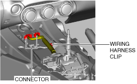
9. Disconnect the connector and wiring harness clip.
amxuuw00002845
|
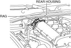
10. Place a clean rag behind the engine so that the engine does not contact the rear housing when it is tilted.
amxzzw00005064
|
11. Remove the front crossmember under cover. (See FRONT CROSSMEMBER UNDER COVER REMOVAL/INSTALLATION.)
12. Disconnect the control rod from the selector lever component. (See AUTOMATIC TRANSMISSION SHIFT MECHANISM REMOVAL/INSTALLATION.)
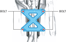
13. Remove the tunnel member.
amxuuw00003817
|
14. Disconnect the HO2S connector. (See HEATED OXYGEN SENSOR (HO2S) REMOVAL/INSTALLATION [SKYACTIV-G 1.5, SKYACTIV-G 2.0].)
15. Disconnect the TWC from the exhaust manifold (WU-TWC). (See EXHAUST SYSTEM REMOVAL/INSTALLATION [SKYACTIV-G 1.5, SKYACTIV-G 2.0].)
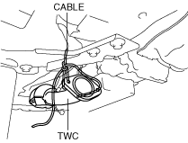
16. Suspend the TWC using a cable as shown in the figure.
amxuuw00002847
|
17. Remove the power plant frame. (See POWER PLANT FRAME REMOVAL [M66M-D].) (See POWER PLANT FRAME INSTALLATION [M66M-D].)
18. Tilt the transmission while being careful not to allow parts on the back of the engine to contact the vehicle body.
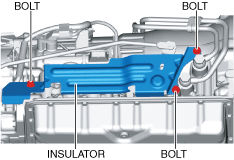
19. Remove the insulator.
amxuuw00002848
|
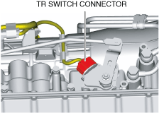
20. Disconnect the TR switch connector.
amxuuw00002849
|
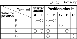
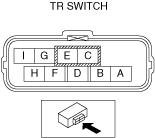
21. Verify that the continuity is as indicated in the table.
amxuuw00003525
|
amxzzw00000190
|
22. Reinspect for continuity at TR switch.