 |
amxuuw00002845
TRANSMISSION RANGE (TR) SWITCH REMOVAL/INSTALLATION [SJ6A-EL]
id051311710200
1. Disconnect the negative battery terminal. (See NEGATIVE BATTERY TERMINAL DISCONNECTION/CONNECTION.)
2. Remove the selector lever knob. (See AUTOMATIC TRANSMISSION SHIFT MECHANISM REMOVAL/INSTALLATION.)
3. Remove the shift panel component. (See SHIFT PANEL REMOVAL/INSTALLATION.)
4. Remove the upper panel. (See UPPER PANEL REMOVAL/INSTALLATION.)
5. Remove the parking brake lever boot panel. (See PARKING BRAKE LEVER BOOT PANEL REMOVAL/INSTALLATION.)
6. Remove the rear console. (See REAR CONSOLE REMOVAL/INSTALLATION.)
7. Remove the front console panel. (See FRONT CONSOLE PANEL REMOVAL/INSTALLATION.)
8. Remove the front console component. (See FRONT CONSOLE REMOVAL/INSTALLATION.)
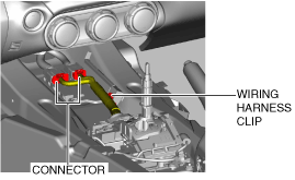
9. Disconnect the connector and wiring harness clip.
amxuuw00002845
|
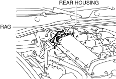
10. Place a clean rag behind the engine so that the engine does not contact the rear housing when it is tilted.
amxzzw00005088
|
11. Remove the front crossmember under cover. (See FRONT CROSSMEMBER UNDER COVER REMOVAL/INSTALLATION.)
12. Disconnect the control rod from the selector lever component. (See AUTOMATIC TRANSMISSION SHIFT MECHANISM REMOVAL/INSTALLATION.)
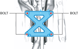
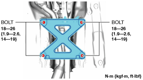
13. Remove the tunnel member.
amxuuw00003817
|
14. Disconnect the HO2S connector. (See HEATED OXYGEN SENSOR (HO2S) REMOVAL/INSTALLATION [SKYACTIV-G 1.5, SKYACTIV-G 2.0].)
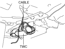
15. Disconnect the TWC from the exhaust manifold (WU-TWC). (See EXHAUST SYSTEM REMOVAL/INSTALLATION [SKYACTIV-G 1.5, SKYACTIV-G 2.0].)
16. Suspend the TWC using a cable as shown in the figure.
amxuuw00002847
|
17. Remove the power plant frame. (See POWER PLANT FRAME REMOVAL [M66M-D].)
18. Tilt the transmission while being careful not to allow parts on the back of the engine to contact the vehicle body.
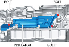
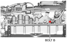
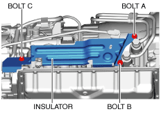
19. Remove the insulator.
amxuuw00002848
|
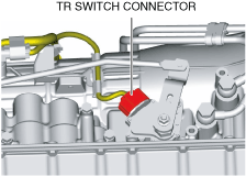
20. Disconnect the TR switch connector.
amxuuw00002849
|
21. Rotate the manual shaft to the N position.
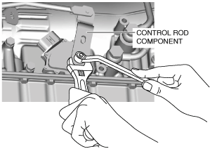
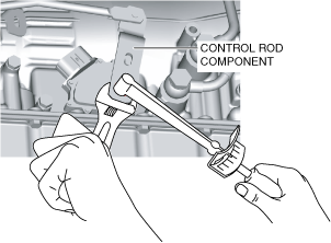
22. Secure the control rod component with an adjustable wrench as shown in the figure.
amxuuw00002850
|
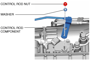
23. Remove the control rod nut.
amxuuw00002851
|
24. Remove the washer and control rod component.
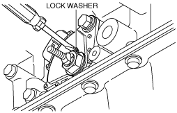
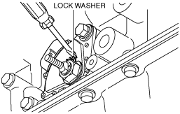
25. Pry off the lock washer using a flathead screwdriver.
amxuuw00002852
|
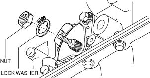
26. Remove the nut and lock washer.
amxzzw00004266
|
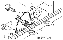
27. Remove the TR switch.
amxuuw00002854
|
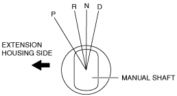
28. Rotate the manual shaft to the extension housing side fully and return two notches to set the N position.
amxuuw00002855
|
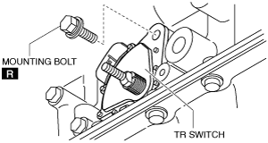
29. Install the TR switch and hand-tighten the new mounting bolts.
amxuuw00002856
|
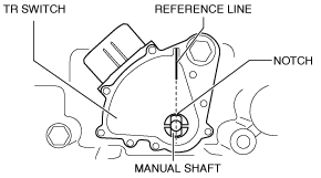
30. Verify the TR switch reference line and the notch of the manual shaft are aligned.
amxuuw00002857
|
31. Install the lock washer with the nut.
amxzzw00004266
|
32. Stake the lock washer using a flathead screwdriver.
amxuuw00002858
|
33. Tighten the TR switch mounting bolts.
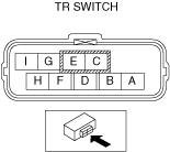
34. Inspect for continuity between TR switch terminals E and H.
amxzzw00000190
|
35. Install the control rod component and washer.
amxuuw00002851
|
36. Secure the control rod component with an adjustable wrench and tighten the control rod nut as shown in the figure.
amxzzw00004471
|
37. Shift the selector lever to the P position.
38. Turn the manual shaft lever to the P position.
39. Inspect TR switch continuity. (See TRANSMISSION RANGE (TR) SWITCH INSPECTION [SJ6A-EL].)
40. Connect the TR switch connector.
amxuuw00002849
|
41. Install the insulator using the following procedure.
amxuuw00002860
|
amxuuw00002861
|
42. Install the power plant frame. (See POWER PLANT FRAME INSTALLATION [M66M-D].)
43. Remove the tunnel member temporarily.
amxuuw00003817
|
44. Connect the TWC to the exhaust manifold (WU-TWC). (See EXHAUST SYSTEM REMOVAL/INSTALLATION [SKYACTIV-G 1.5, SKYACTIV-G 2.0].)
45. Connect the HO2S connector. (See HEATED OXYGEN SENSOR (HO2S) REMOVAL/INSTALLATION [SKYACTIV-G 1.5, SKYACTIV-G 2.0].)
46. Install the tunnel member.
amxuuw00003818
|
47. Connect the control rod from the selector lever component. (See AUTOMATIC TRANSMISSION SHIFT MECHANISM REMOVAL/INSTALLATION.)
48. Install the front crossmember under cover. (See FRONT CROSSMEMBER UNDER COVER REMOVAL/INSTALLATION.)
49. Connect the connector and wiring harness clip.
amxuuw00002845
|
50. Install the front console component. (See FRONT CONSOLE REMOVAL/INSTALLATION.)
51. Install the front console panel. (See FRONT CONSOLE PANEL REMOVAL/INSTALLATION.)
52. Install the rear console. (See REAR CONSOLE REMOVAL/INSTALLATION.)
53. Install the parking brake lever boot panel. (See PARKING BRAKE LEVER BOOT PANEL REMOVAL/INSTALLATION.)
54. Install the upper panel. (See UPPER PANEL REMOVAL/INSTALLATION.)
55. Install the shift panel component. (See SHIFT PANEL REMOVAL/INSTALLATION.)
56. Install the selector lever knob. (See AUTOMATIC TRANSMISSION SHIFT MECHANISM REMOVAL/INSTALLATION.)
57. Connect the negative battery terminal. (See NEGATIVE BATTERY TERMINAL DISCONNECTION/CONNECTION.)
58. Inspect TR switch operation. (See TRANSMISSION RANGE (TR) SWITCH INSPECTION [SJ6A-EL].)
59. Perform the “Initial Learning” (TR switch replacement). (See INITIAL LEARNING PROCEDURE [SJ6A-EL].)