 |
amxzzw00003939
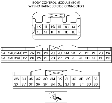
BODY CONTROL MODULE (BCM) INSPECTION
id094000003900
L.H.D
1. Disconnect the negative battery terminal. (See NEGATIVE BATTERY TERMINAL DISCONNECTION/CONNECTION.)
2. Remove the scuff plate (driver's side). (See SCUFF PLATE REMOVAL/INSTALLATION.)
3. Remove the front side trim (driver's side). (See FRONT SIDE TRIM REMOVAL/INSTALLATION.)
4. Remove the BCM. (See BODY CONTROL MODULE (BCM) REMOVAL/INSTALLATION.)
5. Connect the BCM connector.
6. Connect the negative battery terminal. (See NEGATIVE BATTERY TERMINAL DISCONNECTION/CONNECTION.)
7. Verify that the voltages of each of the terminals are as indicated in the terminal voltage table (reference). (See Terminal Voltage Table (Reference).)
R.H.D
1. Disconnect the negative battery terminal. (See NEGATIVE BATTERY TERMINAL DISCONNECTION/CONNECTION.)
2. Remove the following parts:
3. Connect the BCM connector.
4. Connect the negative battery terminal. (See NEGATIVE BATTERY TERMINAL DISCONNECTION/CONNECTION.)
5. Verify that the voltages of each of the terminals are as indicated in the terminal voltage table (reference). (See Terminal Voltage Table (Reference).)
amxzzw00003939
|
Terminal Voltage Table (Reference)
|
Terminal |
Signal |
Connected to |
Measurement condition |
Voltage (V) |
Inspection item(s) |
|
|---|---|---|---|---|---|---|
|
1A
|
Power supply
|
HAZARD 15 A fuse
|
Under any condition
|
B+
|
HAZARD 15 A fuse
|
|
|
1B
|
Power supply
|
• ROOM 25 A fuse
• INTERIOR 15 A fuse
|
Under any condition
|
B+
|
• ROOM 25 A fuse
• INTERIOR 15 A fuse
|
|
|
1C
|
—
|
—
|
—
|
—
|
—
|
|
|
1D*6
|
Brake light control
|
Brake light relay
|
Body control module (BCM) simulation item STOP_LMP_CTL is on
|
1.0 or less
|
Brake light relay
|
|
|
Body control module (BCM) simulation item STOP_LMP_CTL is off
|
B+
|
|||||
|
1E
|
Rear turn light (RH) control
|
Rear turn light (RH)
|
Ignition is switched ON (engine off or on)
|
Turn switch is in right turn position
|
1.0 or less ↔ B+
|
Rear turn light (RH)
|
|
Turn switch is in position other than above
|
1.0 or less
|
|||||
|
1F
|
—
|
—
|
—
|
—
|
—
|
|
|
1G
|
Rear turn light (LH) control
|
Rear turn light (LH)
|
Ignition is switched ON (engine off or on)
|
Turn switch is in left turn position
|
1.0 or less ↔ B+
|
Rear turn light (LH)
|
|
Turn switch is in position other than above
|
1.0 or less
|
|||||
|
1H
|
Interior light power supply
|
Map light
|
Under any condition
|
B+
|
Map light
|
|
|
1I
|
—
|
—
|
—
|
—
|
—
|
|
|
1J
|
—
|
—
|
—
|
—
|
—
|
|
|
1K
|
Ground
|
Body ground
|
Under any condition
|
1.0 or less
|
Body ground
|
|
|
1L
|
Ground
|
Body ground
|
Under any condition
|
1.0 or less
|
Body ground
|
|
|
2A
|
Lock input (door lock-link switch (driver's side))
|
Door latch and lock actuator (driver's side)
|
Driver's door is locked
|
1.0 or less
|
Door latch and lock actuator (driver's side)
|
|
|
Driver's door is unlocked
|
Approx. 10
|
|||||
|
2B
|
Unlock input (door lock-link switch (driver's side))
|
Door latch and lock actuator (driver's side)
|
Driver's door is locked
|
Approx. 9.5
|
Door latch and lock actuator (driver's side)
|
|
|
Driver's door is unlocked
|
1.0 or less
|
|||||
|
2C
|
CAN_L
|
CAN system related module
|
Terminal used for communication therefore determination based on terminal voltage is not possible.
|
|||
|
2D
|
CAN_H
|
CAN system related module
|
Terminal used for communication therefore determination based on terminal voltage is not possible.
|
|||
|
2E
|
Top lock switch signal
|
Top lock switch
|
Convertible top is open
|
1.0 or less
|
Top lock switch
|
|
|
Convertible top is closed
|
Approx. 9.5
|
|||||
|
2F
|
—
|
—
|
—
|
—
|
—
|
|
|
2G
|
Door latch switch (passenger's side) signal
|
Door latch and lock actuator (passenger's side)
|
Door (passenger's side) is open
|
1.0 or less
|
Door latch and lock actuator (passenger's side)
|
|
|
Door (passenger's side) is closed
|
Approx. 9.0
|
|||||
|
2H
|
Door latch switch (driver's side) signal
|
Door latch and lock actuator (driver's side)
|
Door (driver's side) is open
|
1.0 or less
|
Door latch and lock actuator (driver's side)
|
|
|
Door (driver's side) is closed
|
Approx. 9.5
|
|||||
|
2I
|
—
|
—
|
—
|
—
|
—
|
|
|
2J
|
Serial communication
|
Start stop unit
|
Terminal used for communication therefore determination based on terminal voltage is not possible.
|
|||
|
2K*1
|
Door lock switch signal
|
Door lock switch (RH)
|
Door lock switch is turned to unlock side (driver’s side or passenger’s side)
|
1.0 or less
|
Door lock switch (RH)
|
|
|
Door lock switch is turned to lock side (driver’s side or passenger’s side)
|
Approx. 1.25
|
|||||
|
Other
|
Approx 5.0
|
|||||
|
2L
|
Door key cylinder switch signal
|
Door latch and lock actuator (driver’s side)
|
Door key cylinder is turned to unlock side
|
1.0 or less
|
Door latch and lock actuator (driver’s side)
|
|
|
Door key cylinder is turned to lock side
|
Approx. 1.25
|
|||||
|
Other
|
Approx 5.0
|
|||||
|
2M
|
Lock input (door lock-link switch (passenger's side))
|
Door latch and lock actuator (passenger's side)
|
Passenger’s door is unlocked
|
1.0 or less
|
Door latch and lock actuator (passenger's side)
|
|
|
Passenger’s door is locked
|
B+
|
|||||
|
2N
|
—
|
—
|
—
|
—
|
—
|
|
|
2O
|
—
|
—
|
—
|
—
|
—
|
|
|
2P
|
—
|
—
|
—
|
—
|
—
|
|
|
2Q
|
Fuel sensor signal
|
Fuel gauge sender unit
|
Inspect fuel gauge sender unit and related wiring harness because determination based on terminal voltage is not possible.
|
|||
|
2R
|
Fuel sensor ground
|
Fuel gauge sender unit
|
Under any condition
|
1.0 or less
|
Fuel gauge sender unit
|
|
|
2S
|
Trunk lid unlatch switch signal (exterior)
|
Trunk lid opener switch (exterior)
|
Trunk is opened
|
1.0 or less
|
Trunk lid opener switch (exterior)
|
|
|
Trunk is closed
|
Approx. 4.5
|
|||||
|
2T
|
—
|
—
|
—
|
—
|
—
|
|
|
2U
|
—
|
—
|
—
|
—
|
—
|
|
|
2V
|
—
|
—
|
—
|
—
|
—
|
|
|
2W
|
LIN communication
|
Theft-deterrent siren
|
Terminal used for communication therefore determination based on terminal voltage is not possible.
|
|||
|
2X
|
—
|
—
|
—
|
—
|
—
|
|
|
2Y
|
LIN communication
|
Electrical supply unit (ESU)
|
Terminal used for communication therefore determination based on terminal voltage is not possible.
|
|||
|
2Z*6
|
Brake switch signal
|
• Start stop unit
• Brake switch (No.1 signal)
|
Brake pedal is depressed
|
B+
|
• Start stop unit
• Brake switch (No.1 signal)
|
|
|
Brake pedal is not depressed
|
1.0 or less
|
|||||
|
2AA
|
—
|
—
|
—
|
—
|
—
|
|
|
2AB
|
—
|
—
|
—
|
—
|
—
|
|
|
2AC
|
Trunk lid latch switch signal
|
Trunk lid latch and release actuator
|
Trunk is opened
|
1.0 or less
|
Trunk lid latch and release actuator
|
|
|
Trunk is closed
|
Approx. 9.5
|
|||||
|
2AD
|
—
|
—
|
—
|
—
|
—
|
|
|
2AE
|
—
|
—
|
—
|
—
|
—
|
|
|
2AF
|
—
|
—
|
—
|
—
|
—
|
|
|
3A
|
Front turn light (RH) control
|
Front turn light (RH)
|
Ignition is switched ON (engine off or on)
|
Turn switch is in right turn position
|
1.0 or less ↔ B+
|
Front turn light (RH)
|
|
Turn switch is in position other than above
|
1.0 or less
|
|||||
|
3B
|
Front turn light (LH) control
|
Front turn light (LH)
|
Ignition is switched ON (engine off or on)
|
Turn switch is in left turn position
|
1.0 or less ↔ B+
|
Front turn light (LH)
|
|
Turn switch is in position other than above
|
1.0 or less
|
|||||
|
3C
|
CAN_H
|
CAN system related module
|
Terminal used for communication therefore determination based on terminal voltage is not possible.
|
|||
|
3D
|
CAN_L
|
CAN system related module
|
Terminal used for communication therefore determination based on terminal voltage is not possible.
|
|||
|
3E
|
Blower motor relay control
|
• Blower relay
• HEATER 40 A fuse
|
Ignition is switched ON (engine off or on)
|
Blower motor is operated using fan switch
|
1.0 or less
|
• Blower relay
• HEATER 40 A fuse
|
|
Blower motor is turned off by pressing climate control unit OFF button
|
B+
|
|||||
|
3F
|
Windshield wiper INT relay control
|
Wiper INT relay
|
Ignition is switched ON (engine off or on)
|
Windshield wiper switch is in position other than OFF
|
1.0 or less
|
Wiper INT relay
|
|
Windshield wiper switch is in OFF position
|
B+
|
|||||
|
3G
|
Windshield wiper motor (HI) control
|
Wiper HI relay
|
Ignition is switched ON (engine off or on)
|
Windshield wiper switch is in HIGH position
|
1.0 or less
|
Wiper HI relay
|
|
Windshield wiper switch is in OFF position
|
B+
|
|||||
|
3H
|
Horn relay control
|
Horn relay
|
Ignition is switched ON (engine off or on)
|
Horn switch is on
|
1.0 or less
|
Horn relay
|
|
Horn switch is off
|
B+
|
|||||
|
3I
|
—
|
—
|
—
|
—
|
—
|
|
|
3J
|
—
|
—
|
—
|
—
|
—
|
|
|
3J
|
Head light cleaner relay control
|
• Head light cleaner relay
• H/CLEAN 20 A fuse
|
Ignition is switched ON (engine off or on)
|
Connect the M-MDS and turn on the "H/L_CLN_RY" using the body control module (BCM) simulation function
|
1.0 or less
|
• Head light cleaner relay
• H/CLEAN 20 A fuse
|
|
Connect the M-MDS and turn off the "H/L_CLN_RY" using the body control module (BCM) simulation function
|
B+
|
|||||
|
3K
|
Rear window defogger relay control
|
Rear window defogger relay
|
Ignition is switched ON (engine off or on)
|
Rear window defogger switch is on
|
1.0 or less
|
Rear window defogger relay
|
|
Rear window defogger switch is off
|
B+
|
|||||
|
3L
|
—
|
—
|
—
|
—
|
—
|
|
|
3M
|
Autostop switch signal
|
Wiper motor
|
Ignition is switched ON (engine off or on)
|
Windshield wipers are stopped in position other than park
|
1.0 or less
|
Wiper motor
|
|
Windshield wipers are stopped in park position
|
B+
|
|||||
|
3N
|
Power supply
|
• ENG+B 7.5 A fuse
• ROOM 25 A fuse
|
Under any condition
|
B+
|
• ENG+B 7.5 A fuse
• ROOM 25 A fuse
|
|
|
3O
|
Ignition power supply
|
METER1 10 A fuse
|
Ignition is switched ON (engine off or on)
|
B+
|
METER1 10 A fuse
|
|
|
The ignition is switched off (LOCK)
|
1.0 or less
|
|||||
|
3P
|
—
|
—
|
—
|
—
|
—
|
|
|
3Q*2
|
Washer fluid level sensor signal
|
Washer fluid level sensor
|
Ignition is switched ON (engine off or on)
|
Washer fluid level sensor is less than MIN (washer fluid level sensor on)
|
1.0 or less
|
Washer fluid level sensor
|
|
Washer fluid level sensor is MIN or more (Washer fluid level sensor off)
|
B+
|
|||||
|
3R
|
Brake fluid level sensor signal
|
Brake fluid level sensor
|
Ignition is switched ON (engine off or on)
|
Brake fluid level sensor is less than MIN (brake fluid level sensor on)
|
1.0 or less
|
Brake fluid level sensor
|
|
Brake fluid level sensor is MIN or more (brake fluid level sensor off)
|
B+
|
|||||
|
3S
|
LIN communication
|
Current sensor
|
Terminal used for communication therefore determination based on terminal voltage is not possible.
|
|||
|
3T
|
Horn switch control
|
Horn switch
|
Ignition is switched ON (engine off or on)
|
Horn switch is on (long press)
|
1.0 or less
|
Horn switch
|
|
Horn switch is off
|
B+
|
|||||
|
3U
|
Trunk unlatch switch signal (interior)
|
Trunk lid opener switch (interior)
|
Trunk lid opener switch (interior) is on (trunk lid opener switch (interior) is pressed)
|
1.0 or less
|
Trunk lid opener switch (interior)
|
|
|
Trunk lid opener switch (interior) is off (trunk lid opener switch (interior) is not pressed)
|
B+
|
|||||
|
3V
|
—
|
—
|
—
|
—
|
—
|
|
|
3W*4
|
Bonnet latch switch signal
|
Bonnet latch switch
|
Bonnet is open
|
Approx. 9.0
|
Bonnet latch switch
|
|
|
Bonnet is closed
|
1.0 or less
|
|||||
|
3X
|
LIN communication
|
• Auto-light sensor/rain sensor*3
• Theft-deterrenet sensor*5
|
Terminal used for communication therefore determination based on terminal voltage is not possible.
|
|||