FUEL GAUGE SENDER UNIT INSPECTION


id092200012100

Warning
•  Highly pressurized fuel may spray out if the fuel line is cut. Due to the following dangers occurring with a fuel spray, always complete the “Fuel Line Safety Procedure” to prevent the fuel from spraying.
―  Fuel may cause irritation if it comes in contact with skin and eyes.
―  If fuel ignites and causes a fire, it may lead to serious injury or death, and damage to property and facilities.
•  A person charged with static electricity could cause a fire or explosion, resulting in death or serious injury. Before draining fuel, make sure to discharge static electricity by touching the vehicle body.
Caution
•  Disconnecting/connecting the quick release connector without cleaning it may cause damage to the fuel pipe and quick release connector. Always clean the quick release connector joint area before disconnecting/connecting using a cloth or soft brush, and make sure that it is free of foreign material.
Note
•  The fuel gauge sender unit is located in the fuel pump unit. Therefore, when replacing the fuel gauge sender unit, refer to “FUEL PUMP UNIT DISASSEMBLY/ASSEMBLY”. (See FUEL PUMP UNIT DISASSEMBLY/ASSEMBLY [SKYACTIV-G 1.5, SKYACTIV-G 2.0].)

1.  Complete the “BEFORE SERVICE PRECAUTION”. (See BEFORE SERVICE PRECAUTION [SKYACTIV-G 1.5, SKYACTIV-G 2.0].)

2.  If the fuel gauge level indicates 15/16 or more, refer to the “FUEL DRAINING PROCEDURE” and drain the fuel. (See FUEL DRAINING PROCEDURE [SKYACTIV-G 1.5, SKYACTIV-G 2.0].)

3.  Disconnect the negative battery terminal. (See NEGATIVE BATTERY TERMINAL DISCONNECTION/CONNECTION.)

4.  Remove the following parts:

(1)  Seat (LH) (See SEAT REMOVAL/INSTALLATION.)
(2)  Selector lever knob (AT) (See AUTOMATIC TRANSMISSION SHIFT MECHANISM REMOVAL/INSTALLATION.)
(3)  Shift lever knob (MT)
(4)  Shift panel component (See SHIFT PANEL REMOVAL/INSTALLATION.)
(5)  Upper panel (See UPPER PANEL REMOVAL/INSTALLATION.)
(6)  Parking brake lever boot panel (See PARKING BRAKE LEVER BOOT PANEL REMOVAL/INSTALLATION.)
(7)  Rear console (See REAR CONSOLE REMOVAL/INSTALLATION.)
(8)  Scuff plate (See SCUFF PLATE REMOVAL/INSTALLATION.)
(9)  Tire house trim (See TIRE HOUSE TRIM REMOVAL/INSTALLATION.)
(10)  Seat back bar garnish (See SEAT BACK BAR GARNISH REMOVAL/INSTALLATION.)
(11)  Quarter trim (See QUARTER TRIM REMOVAL/INSTALLATION.)
(12)  Wind blocker (See WIND BLOCKER REMOVAL/INSTALLATION.)
(13)  Roof hook lever (See ROOF HOOK REMOVAL/INSTALLATION.)
(14)  Back trim (See BACK TRIM REMOVAL/INSTALLATION.)
(15)  CD player, CD player bracket (with CD player) (See CD PLAYER REMOVAL/INSTALLATION.)
(16)  DVD/CD player, DVD/CD player bracket (with DVD/CD player) (See DVD/CD PLAYER REMOVAL/INSTALLATION.)
(17)  Side shelf (LH) (See SIDE SHELF REMOVAL/INSTALLATION.)
(18)  Rear package trim (See REAR PACKAGE TRIM REMOVAL/INSTALLATION.)
(19)  Fuel pump unit (See FUEL PUMP UNIT REMOVAL/INSTALLATION [SKYACTIV-G 1.5, SKYACTIV-G 2.0].)

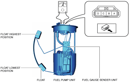
5.  Verify that the resistance between fuel pump unit terminals C and D is as indicated in the table.

amxuuw00004650

Condition of float

Resistance (ohm)

Float is at top position
18.5—21.5
Float is at bottom position
197—203

•  If not within the specification, replace the fuel gauge sender unit. (See FUEL PUMP UNIT DISASSEMBLY/ASSEMBLY [SKYACTIV-G 1.5, SKYACTIV-G 2.0].)