|
1
|
INSPECT DTCs IN SAS CONTROL MODULE
• Is DTC U0001:88 or U0155:00 displayed?
|
Yes
|
Perform the applicable DTC inspection.
|
|
No
|
Go to the next step.
|
|
2
|
PERFORM INSTRUMENT CLUSTER DTC INSPECTION
• Are any DTCs present?
|
Yes
|
Perform the applicable DTC inspection. (See DTC TABLE [INSTRUMENT CLUSTER].) |
|
No
|
Go to the next step.
|
|
3
|
INSPECT INDICATOR UNIT
• Is the indicator unit normal?
|
Yes
|
Go to the next step.
|
|
No
|
Replace the indicator unit.
Then go to Step 9.
|
|
4
|
INSPECT SAS CONTROL MODULE CONNECTOR
-
Warning
-
• Handling the component parts improperly can accidentally operate (deploy) the air bag modules, pre-tensioner seat belts and active bonnet actuators which may seriously injure you. Read the service warnings/cautions and the workshop manual before handling the air bag system components.
• Switch the ignition off.
• Disconnect the negative battery cable and wait for 1 min or more.
• Remove the passenger-side lower panel.
• Disconnect the passenger-side air bag module connector.
• Disconnect the driver and passenger-side seat connectors.
• Disconnect the driver and passenger-side pre-tensioner seat belt connectors.
• Disconnect the driver and passenger-side lap pre-tensioner seat belt connectors.
• Inspect the SAS control module connector terminal for poor connection (such as damaged/pulled-out pins, and corrosion).
• Is there any malfunction?
|
Yes
|
Replace the malfunctioning part, then go to the next step.
|
|
No
|
Go to the next step.
|
|
5
|
INSPECT INSTRUMENT CLUSTER CONNECTOR
• Inspect the instrument cluster terminal for poor connection (such as damaged/pulled-out pins, and corrosion).
• Is there any malfunction?
|
Yes
|
Replace the malfunctioning part, then go to Step 7.
|
|
No
|
Go to the next step.
|
|
6
|
INSPECT INDICATOR UNIT CONNECTOR
• Disconnect the indicator unit connector.
• Inspect the indicator unit terminal for poor connection (such as damaged/pulled-out pins, and corrosion).
• Is there any malfunction?
|
Yes
|
Replace the malfunctioning part, then go to the next step.
|
|
No
|
Go to the next step.
|
|
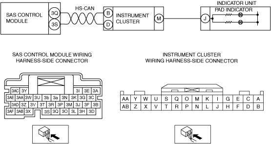
7
|
INSPECT INDICATOR UNIT CIRCUIT FOR OPEN CIRCUIT
• Instrument cluster and indicator unit connectors are disconnected.
• Inspect for continuity between the following terminals (wiring harness-side):
-
― Instrument cluster terminal M—indicator unit terminal J
-
Note
-
• Inspect for continuity while shaking the wiring harness between the instrument cluster and indicator unit.
• Is there continuity?
|
Yes
|
Go to the next step.
|
|
No
|
Refer to the wiring diagram and verify whether or not there is a common connector between indicator unit terminal and instrument cluster terminal.
If there is a common connector:
• Determine the malfunctioning part by inspecting the common connector and the terminal for corrosion, damage, or pin disconnection, and the common wiring harness for an open circuit.
• Replace the malfunctioning part.
If there is no common connector:
• Replace the wiring harness which has an open circuit.
Go to Step 9.
|
|
8
|
INSPECT INDICATOR UNIT CIRCUIT FOR SHORT TO POWER SUPPLY
• Connect the negative battery terminal.
• Switch the ignition ON (engine off or on).
• Instrument cluster and indicator unit connectors are disconnected.
• Measure the voltage at the following terminals (wiring harness-side):
-
― Indicator unit terminal J
-
Note
-
• Measure the voltage while shaking the wiring harness between the instrument cluster and indicator unit.
• Is the voltage 0V?
|
Yes
|
Replace the instrument cluster. (See INSTRUMENT CLUSTER REMOVAL/INSTALLATION.) Then go to the next step.
|
|
No
|
Refer to the wiring diagram and verify whether or not there is a common connector between indicator unit terminal and instrument cluster terminal.
If there is a common connector:
• Determine the malfunctioning part by inspecting the common connector and the terminal for corrosion, damage, or pin disconnection, and the common wiring harness for a short to power supply.
• Replace the malfunctioning part.
If there is no common connector:
• Replace the wiring harness which has a short to power supply.
Go to the next step.
|
|
9
|
PERFORM SAS CONTROL MODULE DTC INSPECTION
• Switch the ignition off.
• Disconnect the negative battery cable and wait for 1 min or more.
• Connect the SAS control module connectors.
• Reconnect all disconnected connectors.
• Connect the negative battery cable.
• Switch the ignition ON (engine off or on).
• Are the same DTCs present?
|
Yes
|
Replace the SAS control module. (See SAS CONTROL MODULE REMOVAL/INSTALLATION.) |
|
No
|
DTC troubleshooting completed.
|