|
1
|
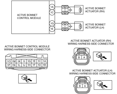
INSPECT CONNECTION CONDITION OF ACTIVE BONNET ACTUATOR (RH)
-
Warning
-
• Handling the component parts improperly can accidentally operate the active bonnet actuator, which may seriously injure you. Read the service warnings and cautions before handling the component parts of the active bonnet.
• Switch the ignition to LOCK.
• Disconnect the negative battery cable and wait 1 min or more.
• Is active bonnet actuator (RH) connector correctly connected?
|
Yes
|
Go to the next step.
|
|
No
|
Connect the active bonnet actuator (RH) connector correctly.
Go to Step 9.
|
|
2
|
ACTIVE BONNET ACTUATOR (RH) CONNECTOR INSPECTION
• Disconnect the active bonnet actuator (RH) connector.
• Inspect the active bonnet actuator (RH) connector. (Corrosion, damage, and disconnected pins)
• Is there any malfunction in the active bonnet actuator (RH) connector?
|
Yes
|
Replace the malfunctioning part, then go to Step 9.
|
|
No
|
Go to the next step.
|
|
3
|
INSPECT ACTIVE BONNET ACTUATOR (RH) CIRCUIT FOR SHORT TO GROUND
• Disconnect the active bonnet actuator (LH) connector.
• Remove the partition board.
• Remove the trunk side trim (RH).
• Disconnect all of the active bonnet control module connectors.
• Inspect for continuity between the following terminals (vehicle wiring harness side) and body ground.
-
― Active bonnet control module terminal 1A
― Active bonnet control module terminal terminal 1C
-
Note
-
• Inspect for continuity while shaking the wiring harness between the active bonnet control module and the active bonnet actuator (RH).
• Is there continuity?
|
Yes
|
Replace the wiring harness, then go to Step 9.
|
|
No
|
Go to the next step.
|
|
4
|
INSPECT ACTIVE BONNET ACTUATOR (RH) CIRCUIT FOR OPEN CIRCUIT
• Verify that the active bonnet actuator and active bonnet control module connectors are disconnected.
• Inspect the wiring harness between the following terminals (vehicle wiring harness side) for continuity.
-
― Active bonnet actuator (RH) terminal A and active bonnet control module terminal 1A
― Active bonnet actuator (RH) terminal B and active bonnet control module terminal 1C
-
Note
-
• Inspect for continuity while shaking the wiring harness between the active bonnet control module and the active bonnet actuator (RH).
• Is there continuity?
|
Yes
|
Go to the next step.
|
|
No
|
Replace the wiring harness, then go to Step 9.
|
|
5
|
SHORT CIRCUIT TO ACTIVE BONNET ACTUATOR (RH) AND (LH) CIRCUITS INSPECTION
• Verify that the active bonnet actuator and active bonnet control module connectors are disconnected.
• Inspect between the following terminals (vehicle wiring harness side) for continuity.
-
― Active bonnet control module terminals 1A and 1G
― Active bonnet control module terminals 1A and 1E
― Active bonnet control module terminals 1C and 1G
― Active bonnet control module terminals 1C and 1E
-
Note
-
• Inspect for continuity while shaking the wiring harness between the active bonnet control module and the active bonnet actuator.
• Is there continuity?
|
Yes
|
Replace the wiring harness, then go to Step 9.
|
|
No
|
Go to the next step.
|
|
6
|
INSPECT FOR SHORT CIRCUIT BETWEEN POWER SUPPLY AND GROUND CIRCUITS OF ACTIVE BONNET ACTUATOR (RH)
• Verify that the active bonnet actuator and active bonnet control module connectors are disconnected.
• Inspect between the following terminals (vehicle wiring harness side) for continuity.
-
― Active bonnet control module terminals 1A and 1C
-
Note
-
• Inspect for continuity while shaking the wiring harness between the active bonnet control module and the active bonnet actuator (RH).
• Is there continuity?
|
Yes
|
Replace the wiring harness, then go to Step 9.
|
|
No
|
Go to the next step.
|
|
7
|
INSPECT ACTIVE BONNET ACTUATOR (RH) CIRCUIT FOR SHORT TO POWER SUPPLY
• Verify that the active bonnet actuator and active bonnet control module connectors are disconnected.
• Connect the negative battery cable.
• Switch the ignition ON.
• Measure the voltage at the following terminals (vehicle wiring harness side).
-
― Active bonnet control module terminal 1A
― Active bonnet control module terminal terminal 1C
-
Note
-
• Measure the voltage while shaking the wiring harness between the active bonnet control module and the active bonnet actuator (RH).
• Is the voltage 0 V?
|
Yes
|
Go to the next step.
|
|
No
|
Replace the wiring harness, then go to Step 9.
|
|
8
|
ACTIVE BONNET ACTUATOR (RH) INSPECTION
• Switch the ignition to LOCK.
• Disconnect the negative battery cable and wait 1 min or more.
• Connect the active bonnet control module connector.
• Connect the active bonnet actuator (LH) connector.
• Connect the SST (Fuel and thermometer checker) or apply 2-ohm resistance to the active bonnet actuator (RH) connector terminals A—B.
• Set the SST (Fuel and thermometer checker) to 2 ohm.
• Connect the negative battery cable.
• Switch the ignition ON.
• Clear the DTC for the active bonnet control module using the M-MDS.
• Perform the active bonnet control module DTC inspection using the M-MDS.
• Is the same DTC displayed?
|
Yes
|
Go to the next step.
|
|
No
|
Replace the active bonnet actuator (RH).
Go to the next step.
|
|
9
|
PERFORM DTC INSPECTION FOR ACTIVE BONNET CONTROL MODULE
• Switch the ignition to LOCK.
• Disconnect the negative battery cable and wait 1 min or more.
• Disconnect the SST (Fuel and thermometer checker) or the 2 ohm resistance.
• Connect the active bonnet actuator (RH) connector.
• Connect the negative battery cable.
• Switch the ignition ON.
• Clear the DTC for the active bonnet control module using the M-MDS.
• Perform the active bonnet control module DTC inspection using the M-MDS.
• Is the same DTC displayed?
|
Yes
|
Replace the active bonnet control module.
|
|
No
|
DTC troubleshooting completed.
|