AUTOMATIC TRANSAXLE REMOVAL/INSTALLATION [FN4A-EL]
id051701802400
-
Caution
-
• Secure the steering wheel using tape or a cable to prevent the steering shaft from rotating after disconnecting the steering shaft. If the steering wheel rotates after the steering shaft and the steering gear and linkage are disconnected, the internal parts of the clock spring could be damaged.
1. Drain the ATF into a separate suitable container. (See AUTOMATIC TRANSAXLE FLUID (ATF) REPLACEMENT [FN4A-EL].)
2. Disconnect and/or remove the following parts.
- (1) Remove the battery, battery tray and battery bracket. (See BATTERY REMOVAL/INSTALLATION [ZJ, ZY].)
- (2) Remove the air cleaner assembly. (See INTAKE-AIR SYSTEM REMOVAL/INSTALLATION [ZJ, ZY].)
- (3) Disconnect the selector cable from the transaxle.
- (4) Disconnect the connector and GND wiring harness from the transaxle.
- (5) Remove the bracket from the transaxle.
- (6) Disconnect the oil hose from the transaxle.
- (7) Remove the filler tube from the transaxle.
- (8) Remove the starter. (See STARTER REMOVAL/INSTALLATION [ZJ, ZY].)
3. Disconnect and/or remove the following parts.
- (1) Remove the front tires. (See GENERAL PROCEDURES (FRONT AND REAR AXLES).)
- (2) Disconnect the ABS wheel-speed sensors from the steering knuckles. (See FRONT ABS WHEEL-SPEED SENSOR REMOVAL/INSTALLATION.) (See REAR ABS WHEEL-SPEED SENSOR REMOVAL/INSTALLATION.)
- (3) Remove the clip, then unlock the brake pipe. (vehicle left side) (See BRAKE HOSE (FRONT) REMOVAL/INSTALLATION.)
- (4) Disconnect the tie-rod end ball joints from the steering knuckles. (See FRONT CROSSMEMBER REMOVAL/INSTALLATION.)
- (5) Disconnect the front lower arm ball joint from the steering knuckles. (See FRONT LOWER ARM REMOVAL/INSTALLATION.)
- (6) Disconnect the stabilizer control links from the shock absorbers. (See FRONT SHOCK ABSORBER AND COIL SPRING REMOVAL/INSTALLATION.)
- (7) Disconnect the drive shaft from the transaxle. (See DRIVE SHAFT REMOVAL/INSTALLATION [ZJ, ZY].)
- (8) Remove the joint shaft. (See JOINT SHAFT REMOVAL/INSTALLATION [ZJ, ZY].)
-
Caution
-
• Refer to the SST instruction manual for the basic handing procedure.
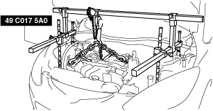
4. Install the SST (49 C017 5A0, 49 UN30 3050) using the following procedure.
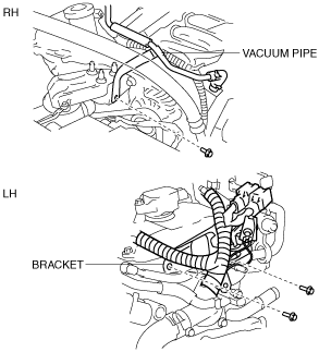
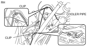
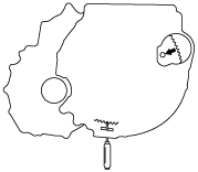
- (1) Set the bracket and vacuum pipe out of the way to prevent interference with the SST as shown in the figure.
-
-
Caution
-
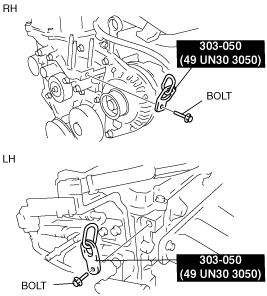
• When attaching the SST in the engine rear side, install a suitable nut between the engine and the SST.
- (2) Using the bolts part number 99794 1025 or M10 × 1.25, length 25 mm {0.98 in} to install the SST to the position as shown in the figure.
-
-
Tightening torque
-
38—51 N·m {3.9—5.2 kgf·m, 29—37 ft·lbf}
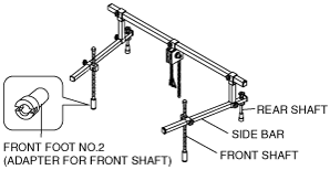
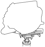
- (3) Install the front foot No.2 to both front shafts of the SST.
-
- (4) Remove the installation nuts for the No.2 reserve tank (L.H.D. only). (See MASTER CYLINDER REMOVAL/INSTALLATION [L.H.D.].)
- (5) Set the No.2 reserve tank out of the way to prevent interference with the rear shaft of the SST (left side) (L.H.D. only).
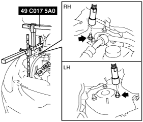
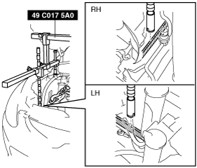
- (6) Install both rear shafts of the SST to the bolt of both shock absorbers as shown in the figure.
-
- (7) Set the cooler pipe out of the way to prevent interference with the front shaft of the SST as shown in the figure.
-
- (8) Set the front combination light connector out of the way to prevent interference with the front shafts of the SST as shown in the figure.
-
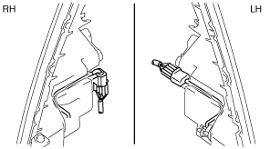
- (9) Insert front shafts into the shroud panel in the position shown in the figure.
-
- (10) Adjust the positions of the SST side bars so that they are the same height (left and right) and horizontal.
-
- (11) Make sure each joint is securely tightened.
-
Warning
-
• Improperly jacking a transaxle is dangerous. It can slip off the jack and may cause serious injury.
-
Caution
-
• To prevent the torque converter and transaxle from separating, remove the transaxle without tilting it toward the torque converter.
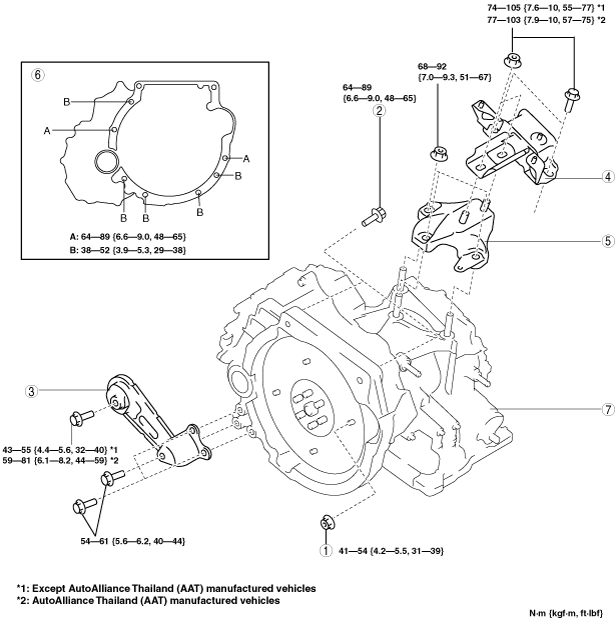
5. Remove in the order shown in the figure.
6. Install in the reverse order of removal.
7. Add the ATF. (See AUTOMATIC TRANSAXLE FLUID (ATF) REPLACEMENT [FN4A-EL].)
8. Perform the following test according to the service item. (See MECHANICAL SYSTEM TEST [FN4A-EL].) (See ROAD TEST [FN4A-EL].)
|
Service item
|
Test item
|
|
Line pressure test
|
Stall test
|
Time lag test
|
Road test
|
|
ATX replacement
|
X
|
|
|
|
|
ATX overhaul
|
X
|
X
|
X
|
X
|
|
Torque converter replacement
|
X
|
X
|
|
|
|
Oil pump replacement
|
X
|
|
|
|
|
Clutch system replacement
|
X
|
|
X
|
X
|
X :Test to be performed after the service work
|
1
|
Torque converter installation nuts
|
|
2
|
Transaxle mounting bolts (upper side)
|
|
3
|
No.1 engine mount
|
|
4
|
No.4 engine mount rubber
|
|
5
|
No.4 engine mount bracket
|
|
6
|
Transaxle mounting bolts (lower side)
|
|
7
|
Transaxle
|
Torque Converter Installation Nuts Removal Note
1. Using the flathead screwdriver, lock the drive plate.
2. Remove the torque converter nuts from the starter installation hole.
Transaxle Installation Bolts (Lower Side) Removal Note
1. Adjust the SST (49 C017 5A0) and lean the engine toward the transaxle.
2. Support the transaxle on a jack.
3. Remove the transaxle mounting bolts.
4. Remove the transaxle.
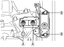
No.4 Engine Mount Rubber Installation Note
1. Tighten nuts and bolts in the order of A to B.
-
Tightening torque
-
Except AutoAlliance Thailand (AAT) manufactured vehicles: 74—105 N·m {7.6—10 kgf·m, 55—77 ft·lbf}
AutoAlliance Thailand (AAT) manufactured vehicles: 77—103 N·m {7.9—10 kgf·m, 57—75 ft·lbf}
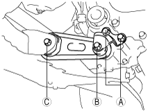
No.1 Engine Mount Installation Note
1. Tighten bolt in the order of A to C.
-
Tightening torque
-
A, B:54—61 N·m {5.5—6.2 kgf·m, 40—44 ft·lbf}
C:43—55 N·m {4.4—5.6 kgf·m, 32—40 ft·lbf}*1
C:59—81 N·m {6.1—8.2 kgf·m, 44—59 ft·lbf}*2
*1 :Except AutoAlliance Thailand (AAT) manufactured vehicles
*2 :AutoAlliance Thailand (AAT) manufactured vehicles