 |
am2zzw00003029
CAMSHAFT REMOVAL/INSTALLATION [MZ-CD 1.4 DI Turbo]
id0110b8811000
1. Disconnect the negative battery cable. (See BATTERY REMOVAL/INSTALLATION [MZ-CD 1.4 DI Turbo].)
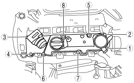
2. Remove the following parts:
3. Remove the wiring harness and wiring harness bracket from the upper timing belt cover.
4. Set the cooler hose out of the way (With A/C). (See REFRIGERANT LINE REMOVAL/INSTALLATION.)
5. Remove the intake-air system. (See INTAKE-AIR SYSTEM REMOVAL/INSTALLATION [MZ-CD 1.4 DI Turbo].)
6. Remove the timing belt. (See TIMING BELT REMOVAL/INSTALLATION [MZ-CD 1.4 DI Turbo].)
7. Remove the vacuum pump. (See VACUUM PUMP REMOVAL/INSTALLATION [MZ-CD 1.4 DI Turbo].)
8. Disconnect the fuel pressure sensor / glow plug / fuel injector connector.
am2zzw00003029
|
9. Disconnect the EGR valve connector.
10. Set the EGR valve and EGR cooler as a single unit out of the way. (See EGR VALVE REMOVAL/INSTALLATION [MZ-CD 1.4 DI Turbo].)
11. Set the fuel return hose out of the way.
12. Remove the CMP sensor. (See CAMSHAFT POSITION (CMP) SENSOR REMOVAL/INSTALLATION [MZ-CD 1.4 DI Turbo].)
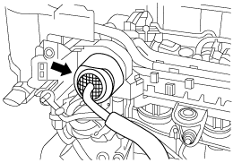
13. Disconnect the MAP sensor hose (cylinder head cover side).
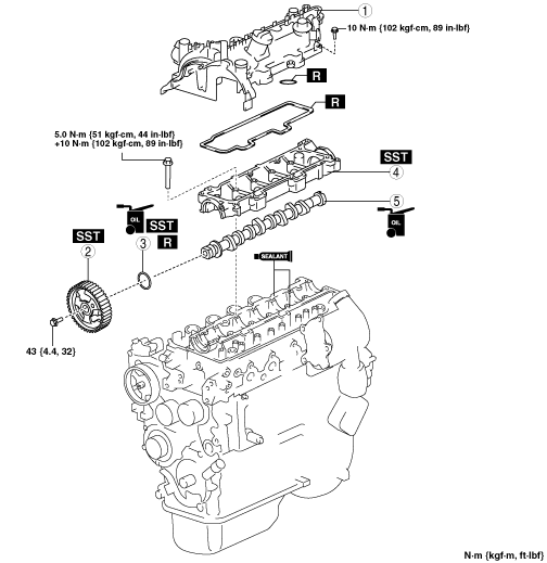
14. Remove in the order indicated in the table.
15. Install in the reverse order of removal.
16. Start the engine.
17. Inspect the following and adjust if necessary.
am2zzw00003080
|
|
1
|
Cylinder head cover
|
|
2
|
Camshaft pulley
(See Camshaft Pulley Removal Note.)
|
|
3
|
Camshaft oil seal
|
|
4
|
Camshaft housing (upper)
|
|
5
|
Camshaft
|
Cylinder Head Cover Removal Note
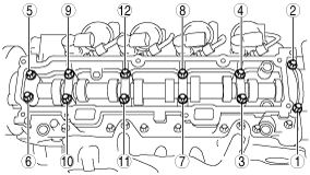
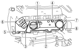
1. Remove the cylinder head cover installation bolts in the order shown in the figure.
am2zzw00003110
|
Camshaft Pulley Removal Note
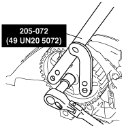
1. Lock the camshaft using the SSTs.
am2zzw00001111
|
2. Remove the camshaft pulley installation bolt.
Camshaft Housing (Upper) Removal Note
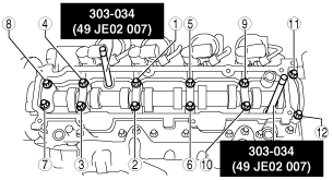
1. Remove the camshaft housing (upper) installation bolts in the order shown in the figure.
am2zzw00003081
|
Camshaft Housing (Upper) Installation Note
1. Clean the mating surfaces of the camshaft housing (lower) and camshaft housing (upper) with Loctite 7070 or equivalent.
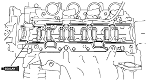
2. Apply the sealant to the mating surface of the camshaft housing (lower).
am2zzw00003082
|
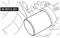
3. Align the camshaft housing (upper) to the camshaft housing (lower) using the SSTs.
am2zzw00003083
|
4. Tighten the camshaft housing (upper) installation bolts in two steps in the order shown in the figure.
Camshaft Oil Seal Installation Note
1. Apply clean engine oil to a new camshaft oil seal.
2. Install the camshaft oil seal using the SST.
am3zzw00001385
|
Camshaft Pulley Installation Note
1. Lock the camshaft using the SSTs.
am2zzw00001111
|
2. Tighten the camshaft pulley installation bolt.
Cylinder Head Cover Installation Note
1. Tighten the cylinder head cover installation bolts in the order shown in the figure.
am2zzw00002742
|