1. Disconnect the negative battery cable.
2. Remove the battery, battery tray and battery tray bracket.
3. Remove the air cleaner cover. (See INTAKE-AIR SYSTEM REMOVAL/INSTALLATION [WITH WU-TWC].) (See INTAKE-AIR SYSTEM REMOVAL/INSTALLATION [WITHOUT WU-TWC].)
4. Remove the console.
5. Remove the rear heat duct. (See REAR HEAT DUCT REMOVAL/INSTALLATION.)
6. Remove the dashboard completely.
(See DASHBOARD REMOVAL/INSTALLATION.)
7. Remove the A/C unit. (See A/C UNIT REMOVAL/INSTALLATION.)
8. Remove the wiring harness of the SAS unit.
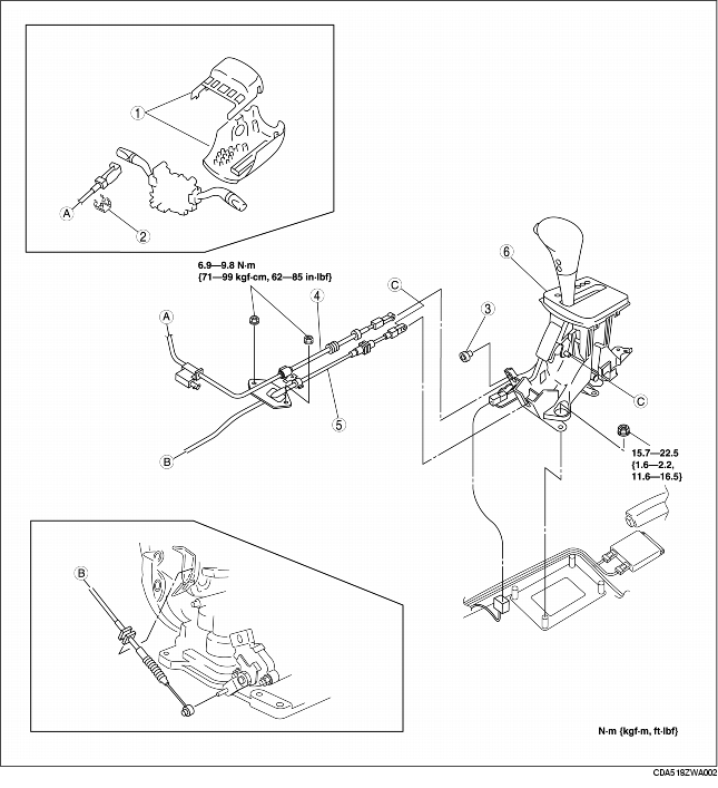
9. Remove in the order shown in the figure.
10. Install in the reverse order of removal.
|
1
|
Column cover
|
|
2
|
Clip
|
|
3
|
Clip
|
|
4
|
Interlock cable
|
|
5
|
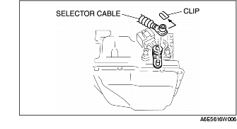
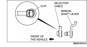
Selector cable
(See Selector Cable Removal Note.)
|
|
6
|
Selector lever
|
1. Remove the clip.
2. Remove the selector cable.
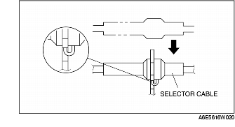
1. Install the selector cable to the selector lever securely.
2. Install the selector cable to the bracket securely.
3. Verify that the selector lever is in the P position.
4. Verify that the manual shaft is in the P position.
5. Install the selector lever to the manual shaft lever in such a way that the selector cable does not bear a load.
6. Confirm that the end of the manual shift lever sticks out of the end of the selector cable.
7. Install the selector cable to the selector cable bracket securely.
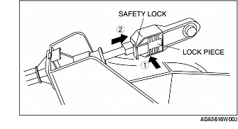
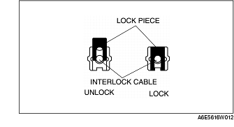
8. Lock the lock piece of the selector cable (selector lever side) in the order shown in the figure.
1. Verify that the selector lever is in P position.
2. Depress the brake pedal.
3. Disconnect the brake switch connector.
4. Replace the brake switch with a new one.
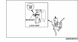
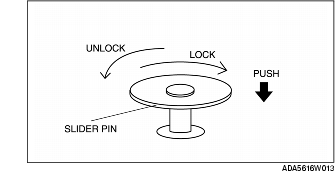
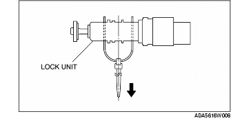
5. From this position, slide the lock unit to fix the lock unit hook into the bracket hole securely as shown in the figure.
6. Verify that the slider pin can turn freely.
7. With the brake pedal released, push the slider pin to the stopper plate and rotate to lock.
8. Connect the brake switch connector when return the brake pedal with certainty.
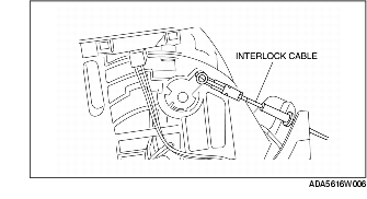
9. Install the interlock cable end onto the cam pin on the selector lever.
10. Fit the interlock cable in the U-groove in the selector lever base plate, and install the clip.
11. Press the interlock cable lock piece in until it is locked.
12. Remove the lock unit pin as shown in the figure.
13. Turn the ignition switch to the ACC position.
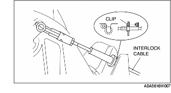
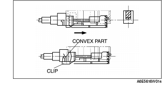
14. Install the interlock cable to the key cylinder.
15. Slide the outer casing to the key cylinder, and insert the clip over the convex part of the outer casing.
16. After installation, carry out the shift-lock inspection, interlock inspection and brake switch inspection.
(See SHIFT-LOCK INSPECTION.)
(See KEY INTERLOCK INSPECTION.)
(See BRAKE SWITCH INSPECTION.)