HYDRAULIC LASH ADJUSTER (HLA) REMOVAL/INSTALLATION [MZ-CD 1.6]


id0110e3804100

Warning
•  Fuel vapor is hazardous. It can very easily ignite, causing serious injury and damage. Always keep sparks and flames away from fuel.
•  Fuel line spills and leakage are dangerous. Fuel can ignite and cause serious injuries or death and damage. Fuel can also irritate skin and eyes. To prevent this, always complete the “Fuel Line Safety Procedure”. (See BEFORE SERVICE PRECAUTION [MZ-CD 1.6].)

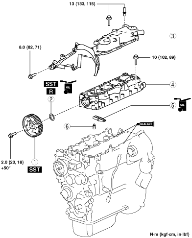
1.  Remove the following parts:

(1)  Timing belt (See TIMING BELT REMOVAL/INSTALLATION [MZ-CD 1.6].)
(2)  Fuel injectors (See FUEL INJECTOR REMOVAL/INSTALLATION [MZ-CD 1.6].)
(3)  Fuel filter protector and fuel filter (See FUEL FILTER REMOVAL/INSTALLATION [MZ-CD 1.6].)
(4)  Charge air cooler outlet hose, intake shutter valve, intake air pipe No.2 and hose (See INTAKE-AIR SYSTEM REMOVAL/INSTALLATION [MZ-CD 1.6].)
(5)  Charge air cooler inlet hose and intake air pipe No.1(See INTAKE-AIR SYSTEM REMOVAL/INSTALLATION [MZ-CD 1.6].)
(6)  CMP sensor (See CAMSHAFT POSITION (CMP) SENSOR REMOVAL/INSTALLATION [MZ-CD 1.6].)
(7)  Vacuum pump (See VACUUM PUMP REMOVAL/INSTALLATION [MZ-CD 1.6].)

2.  Remove in the order indicated in the table.

3.  Install in the reverse order of removal.

4.  Start the engine.

5.  Inspect the following and adjust them if necessary.

(1)  Pulley and belt for runout and contact

am2zzw00006433

1
Camshaft pulley
2
Camshaft oil seal
3
Cylinder head cover
4
Upper Cylinder head
5
Rocker arm
6
HLA


Camshaft Pulley Removal Note

1.  Lock the camshaft pulley using the SSTs.

am2zzw00007010

2.  Remove the camshaft pulley installation bolt.


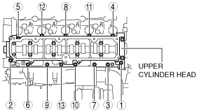
Upper Cylinder Head Removal Note

1.  Remove the upper cylinder head installation bolts in the order shown in the figure.

am2zzw00006971


Rocker Arm And HLA Removal Note

Caution
•  Keep the rocker arms and HLAs in order for re-installation.

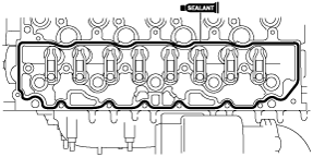
Upper Cylinder Head Installation Note

1.  Clean the mating surfaces of the upper cylinder head and lower cylinder head.

2.  Apply the sealant to the mating surface of the lower cylinder head.

Caution
•  Install the upper cylinder head before the applied silicone sealant starts to harden.
am2zzw00006972

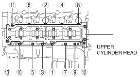
3.  Tighten the upper cylinder head installation bolts in two steps in the order shown in the figure.

am2zzw00006973

Tightening torque
10 N·m {102 kgf·cm, 89 in·lbf}


Camshaft Oil Seal Installation Note

Note
•  A new camshaft oil seal is supplied with an alignment and protection sleeve that must be removed during the following installation.

1.  Apply clean engine oil to a new camshaft oil seal.

2.  Install the camshaft oil seal using the SST.

am2zzw00006974


Camshaft Pulley Installation Note

1.  Lock the camshaft using the SSTs.

am2zzw00007010

2.  Tighten the camshaft pulley installation bolt.

Tightening torque
1.  2.0 N·m {20 kgf·cm, 18 in·lbf}
2.  50°