 |
am2zzw00005863
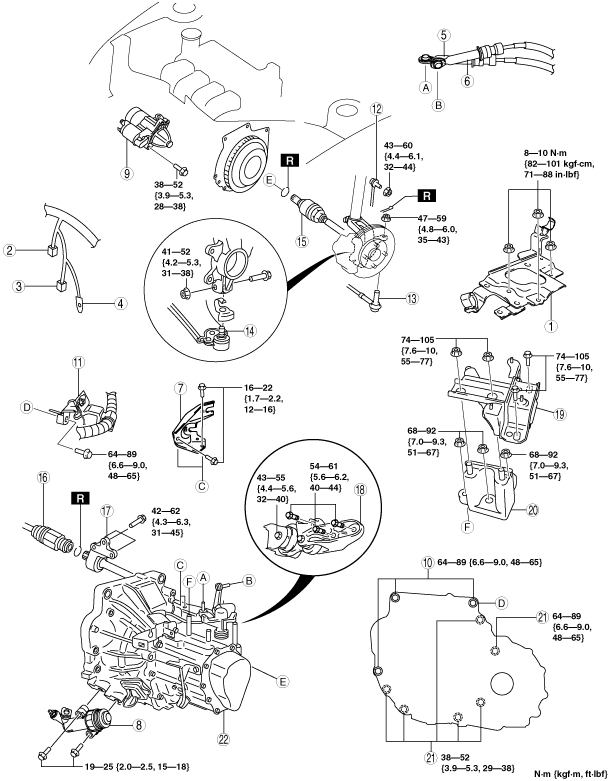
MANUAL TRANSAXLE REMOVAL/INSTALLATION [F35M-R]
id0515a1800600
1. Remove the battery and battery tray and battery bracket. (See BATTERY REMOVAL/INSTALLATION [MZR 1.3, MZR 1.5].)
2. Remove the front wheels and tires. (See GENERAL PROCEDURES (FRONT AND REAR AXLES).)
3. Remove the fresh-air duct and air cleaner component as a single unit. (See INTAKE-AIR SYSTEM REMOVAL/INSTALLATION [MZR 1.3, MZR 1.5].)
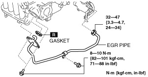
4. Remove the EGR pipe installation bolt. (intake manifold side) (See EGR PIPE REMOVAL/INSTALLATION [MZR 1.3, MZR 1.5].)
am2zzw00005863
|
5. Suspend the EGR pipe (intake manifold side) with a cable in place out of the way.
am2zzw00000186
|
6. Drain the transaxle oil into a suitable container. (See TRANSAXLE OIL REPLACEMENT [F35M-R].)
7. Remove in the order indicated in the table.
8. Install in the reverse order of removal.
9. Add the specified amount of specified transaxle oil. (See TRANSAXLE OIL REPLACEMENT [F35M-R].)
am2zzw00005704
|
|
1
|
Battery tray bracket
|
|
2
|
Neutral switch connector
|
|
3
|
Back-up light switch connector
|
|
4
|
Ground
|
|
5
|
Shift cable
|
|
6
|
Select cable
|
|
7
|
Select cable bracket
|
|
8
|
Clutch release cylinder
|
|
9
|
Starter
|
|
10
|
Transaxle mounting bolt (upper side)
|
|
11
|
Wiring harness bracket
|
|
12
|
Stabilizer control link
|
|
13
|
Tie-rod end ball joint
|
|
14
|
Lower arm ball joint
|
|
15
|
Drive shaft (LH)
|
|
16
|
Drive shaft (RH)
|
|
17
|
Joint shaft
|
|
18
|
No.1 engine mount
|
|
19
|
No.4 engine mount rubber
|
|
20
|
No.4 engine mount bracket
|
|
21
|
Transaxle mounting bolt (lower side)
|
|
22
|
Manual transaxle
|
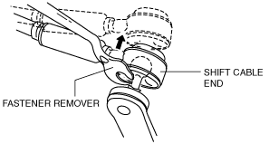
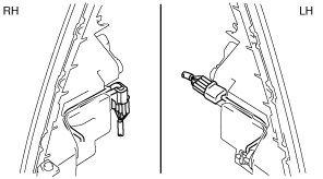
Shift Cable and Select Cable Removal Note
1. Remove the both shift cable end and select cable end using a fastener remover.
am2zzw00000188
|
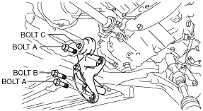
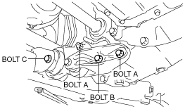
No.1 Engine Mount Removal Note
1. Remove the bolt A, B.
2. Loosen bolt C and slide engine mount No.1 as shown in the figure.
am2zzw00001494
|
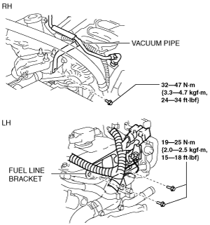
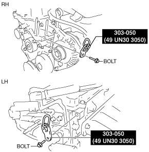
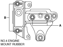
No.4 Engine Mount Rubber Removal Note
1. Set the bracket and vacuum pipe shown in the figure out of the way to prevent interference with the SST.
am2zzw00005705
|
2. Using the bolts part number 99794 1025 or M10×1.25, length 25 mm {0.98 in} to install the SST (49 UN30 3050) to the position shown in the figure.
am2zzw00005706
|
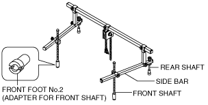
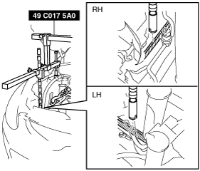
3. Install front foot No.2 to the left/right front shaft of the SST (49 C017 5A0).
am2zzw00000191
|
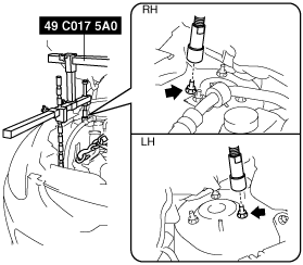
4. As shown in the figure, set the rear shafts of the SST to the left and right shock absorber upper bolts.
L.H.D.
am2zzw00005707
|
R.H.D.
am2zzw00005708
|
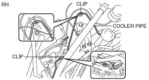
5. Remove the cooler pipe from the clips and set it out of the way to prevent interference between the SST and the front shaft.
am2zzw00005709
|
6. Set the front combination light connector out of the way to prevent interference with the front shaft of the SST as shown in the figure.
am2zzw00005710
|
7. As shown in the figure, set the front shaft groove of the SST to the folded part of the left and right body frames.
am2zzw00005711
|
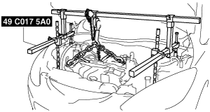
8. Adjust the height of the left and right side bars so that they are leveled, then tighten each part of the SST.
am2zzw00000196
|
9. Verify that the SST is properly set and the engine is securely hung.
10. Remove the No.4 engine mount.
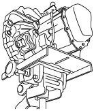
Manual Transaxle Removal Note
1. Adjust the SST and lean the engine toward the transaxle.
am2zzw00000196
|
2. Support the transaxle on a jack.
am2zzw00000198
|
3. Remove the transaxle mounting bolts.
4. Remove the transaxle.
Manual Transaxle Installation Note
1. Set the transaxle on a jack and lift into place.
2. Install the transaxle mounting bolts.
am2zzw00001941
|
3. Adjust the SST (49 C017 5A0) so that the engine is located at the specified position.
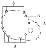
No.4 Engine Mount Rubber Installation Note
1. Tighten the nuts and bolts in the order of A to B.
am2zzw00000200
|
No.1 Engine Mount Installation Note
1. Adjust the SST (engine support), and align the hole of the No.1 engine mount with the bolt hole of transaxle.
2. Tighten the bolt A, B.
am2zzw00001495
|
3. Tighten the bolt C.