 |
am2zzw00006117
DTC U3003:16, U3003:17 [ADVANCED KEYLESS AND START SYSTEM]
id0902e1399400
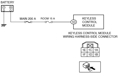
L.H.D.
Description
Possible Causes
System Wiring Diagram
am2zzw00006117
|
Diagnostic Procedure
|
Step |
Inspection |
Action |
|
|---|---|---|---|
|
1
|
VERIFY PCM DTC
• Perform the PCM DTC inspection using the M-MDS.
(See MZ-CD 1.6.)
• Are any DTCs present?
|
Yes
|
Go to the applicable DTC inspection.
(See DTC TABLE [MZR 1.3, MZR 1.5].)
(See MZ-CD 1.6.)
|
|
No
|
Go to the next step.
|
||
|
2
|
INSPECT BATTERY
• Inspect the battery.
• Is there any malfunction?
|
Yes
|
Recharge or replace the battery, then go to Step 6.
|
|
No
|
Go to the next step.
|
||
|
3
|
INSPECT GENERATOR
• Inspect the generator.
• Is there any malfunction?
|
Yes
|
Replace the generator, then go to Step 6.
|
|
No
|
Go to the next step.
|
||
|
4
|
INSPECT KEYLESS CONTROL MODULE CONNECTOR AND TERMINALS
• Disconnect the negative battery cable.
• Disconnect the keyless control module connector.
• Inspect the connector and terminals (corrosion, damage, pin disconnection).
• Is there any malfunction?
|
Yes
|
Repair or replace the connector or terminals, then go to Step 6.
|
|
No
|
Go to the next step.
|
||
|
5
|
INSPECT KEYLESS CONTROL MODULE POWER SUPPLY CIRCUIT FOR OPEN CIRCUIT OR SHORT TO GROUND
• Verify that the keyless control module connector is disconnected.
• Reconnect the negative battery cable.
• Measure the voltage at the keyless control module terminal 1D (wiring harness-side).
• Is the voltage B+?
|
Yes
|
Go to the next step.
|
|
No
|
Inspect the ROOM 15 A fuse and MAIN 200 A.
• If the fuse is melt:
• If the fuse is deterioration:
• If the fuse is normal:
Go to the next step.
|
||
|
6
|
VERIFY TROUBLESHOOTING COMPLETED
• Make sure to reconnect all disconnected connectors.
• Reconnect the negative battery cable.
• Clear the DTCs using the M-MDS.
• Perform the keyless control module DTC inspection using the M-MDS.
• Is the same DTC present?
|
Yes
|
Repeat the inspection from Step 1.
• If the malfunction recurs, replace the keyless control module.
Go to the next step.
|
|
No
|
Go to the next step.
|
||
|
7
|
VERIFY THAT NO OTHER DTCs ARE PRESENT
• Are any DTCs present?
|
Yes
|
Go to the applicable DTC inspection.
|
|
No
|
DTC troubleshooting completed.
|
||
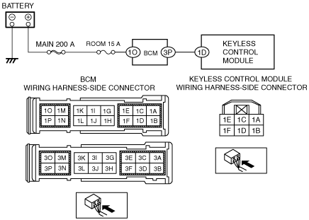
R.H.D.
Description
Possible Causes
System Wiring Diagram
am2zzw00006118
|
Diagnostic Procedure
|
Step |
Inspection |
Action |
|
|---|---|---|---|
|
1
|
VERIFY PCM DTC
• Perform the PCM DTC inspection using the M-MDS.
(See MZ-CD 1.6.)
• Are any DTCs present?
|
Yes
|
Go to the applicable DTC inspection.
(See DTC TABLE [MZR 1.3, MZR 1.5].)
(See MZ-CD 1.6.)
|
|
No
|
Go to the next step.
|
||
|
2
|
INSPECT BATTERY
• Inspect the battery.
• Is there any malfunction?
|
Yes
|
Recharge or replace the battery, then go to Step 9.
|
|
No
|
Go to the next step.
|
||
|
3
|
INSPECT GENERATOR
• Inspect the generator.
• Is there any malfunction?
|
Yes
|
Replace the generator, then go to Step 9.
|
|
No
|
Go to the next step.
|
||
|
4
|
INSPECT BCM CONNECTOR AND TERMINALS
• Turn the ignition switch to the LOCK position.
• Disconnect the negative battery cable.
• Disconnect the BCM connector.
• Inspect the connector and terminals (corrosion, damage, pin disconnection).
• Is there any malfunction?
|
Yes
|
Repair or replace the connector or terminals, then go to Step 9.
|
|
No
|
Go to the next step.
|
||
|
5
|
INSPECT KEYLESS CONTROL MODULE POWER SUPPLY CIRCUIT FOR OPEN CIRCUIT OR SHORT TO GROUND
• Verify that the BCM connector is disconnected.
• Reconnect the negative battery cable.
• Measure the voltage at the BCM terminal 1O (wiring harness-side).
• Is the voltage B+?
|
Yes
|
Go to the next step.
|
|
No
|
Inspect the ROOM 15 A fuse and MAIN 200 A.
• If the fuse is melt:
• If the fuse is deterioration:
• If the fuse is normal:
Go to Step 9.
|
||
|
6
|
INSPECT BCM
• Disconnect the negative battery cable.
• Make sure to reconnect all disconnected connectors.
• Reconnect the negative battery cable.
• Measure the voltage at the following terminals (wiring harness-side):
• Is the voltage normal?
|
Yes
|
Go to the next step.
|
|
No
|
Replace the BCM, then go to Step 9.
|
||
|
7
|
INSPECT KEYLESS CONTROL MODULE CONNECTOR AND TERMINALS
• Disconnect the negative battery cable.
• Disconnect the keyless control module connector.
• Inspect the connector and terminals (corrosion, damage, pin disconnection).
• Is there any malfunction?
|
Yes
|
Repair or replace the connector or terminals, then go to Step 9.
|
|
No
|
Go to the next step.
|
||
|
8
|
INSPECT KEYLESS CONTROL MODULE POWER SUPPLY CIRCUIT FOR OPEN CIRCUIT OR SHORT TO GROUND
• Verify that the keyless control module connector is disconnected.
• Measure the voltage at the keyless control module terminal 1D (wiring harness-side).
• Is the voltage B+?
|
Yes
|
Go to the next step.
|
|
No
|
Repair or replace the wiring harness for a possible open circuit or short to ground, then go to the next step.
|
||
|
9
|
VERIFY TROUBLESHOOTING COMPLETED
• Make sure to reconnect all disconnected connectors.
• Reconnect the negative battery cable.
• Clear the DTCs using the M-MDS.
• Perform the keyless control module DTC inspection using the M-MDS.
• Is the same DTC present?
|
Yes
|
Repeat the inspection from Step 1.
• If the malfunction recurs, replace the keyless control module.
Go to the next step.
|
|
No
|
Go to the next step.
|
||
|
10
|
VERIFY THAT NO OTHER DTCs ARE PRESENT
• Are any DTCs present?
|
Yes
|
Go to the applicable DTC inspection.
|
|
No
|
DTC troubleshooting completed.
|
||