THEFT-DETERRENT CONTROL MODULE REMOVAL/INSTALLATION
id091400820800
-
Caution
-
• When replacing the theft-deterrent control module, always perform the configuration procedure before removing the theft-deterrent control module. Replacing the theft-deterrent control module without performing the configuration procedure will result in system malfunction.
1. When replacing the theft-deterrnet control module, always perform the configuration procedure. (See THEFT-DETERRENT CONTROL MODULE CONFIGURATION.)
2. Disconnect the negative battery cable.
3. Remove the following parts:
- (1) Front scuff plate (driver's side)(5HB) (See FRONT SCUFF PLATE REMOVAL/INSTALLATION.)
- (2) Front scuff plate (driver's side)(3HB) (See FRONT SCUFF PLATE REMOVAL/INSTALLATION [3HB].)
- (3) Front side trim (driver's side) (See FRONT SIDE TRIM REMOVAL/INSTALLATION.)
- (4) Rear console (L.H.D.)(See REAR CONSOLE REMOVAL/INSTALLATION.)
- (5) Shift lever knob (MTX) (See MANUAL TRANSAXLE SHIFT MECHANISM REMOVAL/INSTALLATION [F35M-R].)(See MANUAL TRANSAXLE SHIFT MECHANISM REMOVAL/INSTALLATION [B65M-R].)
- (6) Side wall (See SIDE WALL REMOVAL/INSTALLATION.)
- (7) Front console component (See FRONT CONSOLE COMPONENT REMOVAL/INSTALLATION.)
- (8) Bonnet release lever (See BONNET LATCH AND RELEASE LEVER REMOVAL/INSTALLATION.)
- (9) Lower panel (Driver’s side) (See LOWER PANEL REMOVAL/INSTALLATION.)
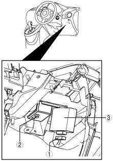
4. Remove in the order indicated in the table.
|
1
|
Connector
|
|
2
|
Bolt
|
|
3
|
Theft-deterrent control module
|
5. Install in the reverse order of removal.