 |
am2zzw00000596
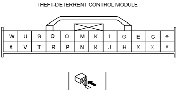
THEFT-DETERRENT CONTROL MODULE INSPECTION
id091400820900
1. Remove the following parts:
2. Measure the voltage according to the terminal voltage table.
Terminal Voltage Table (Reference)
am2zzw00000596
|
|
Terminal |
Signal name |
Connected to |
Measurement condition |
Voltage (V) |
Inspection item(s) |
|---|---|---|---|---|---|
|
C
|
• Intruder sensor signal
• Theft-deterrent siren signal
|
• Intruder sensor
• Theft-deterrent siren
|
Terminal used for communication therefore determination based on terminal voltage inspection not possible.
|
||
|
E
|
Start knob (push switch)
|
Steering lock unit (with advanced keyless system)
|
Start knob is pushed
|
B+
|
• Steering lock unit (with advanced keyless system)
• Related wiring harnesses
|
|
Other
|
1.0 or less
|
||||
|
G
|
Key reminder switch signal*2
|
Key reminder switch (with keyless entry system)
|
Key inserted
|
B+
|
• Key reminder switch (with keyless entry system)
• Related wiring harnesses
|
|
Key removed
|
1.0 or less
|
||||
|
Push switch signal
|
Steering lock unit (with advanced keyless system)
|
Start knob is pressed
|
B+
|
• Steering lock unit (with advanced keyless system)
• Related wiring harnesses
|
|
|
Start knob is not pressed
|
1.0 or less
|
||||
|
H
|
Bonnet latch switch signal
|
Bonnet latch switch
|
Bonnet open (Bonnet latch switch off)
|
Wave pattern (See Pattern 1.)
|
• Bonnet latch switch
• Related wiring harnesses
|
|
Bonnet closed (Bonnet latch switch on)
|
1.0 or less
|
||||
|
I
|
CAN_L
|
-
|
Terminal used for communication therefore determination based on terminal voltage inspection not possible.
|
||
|
J
|
GND
|
Ground
|
Under any condition
|
1.0 or less
|
• Related wiring harnesses
|
|
K
|
CAN_H
|
-
|
Terminal used for communication therefore determination based on terminal voltage inspection not possible.
|
||
|
M*2
|
Front door latch switch (passenger's door) signal
|
Front door latch switch (passenger's door)
|
Front door (passenger-side) open (Front door switch (passenger' door) off)
|
Wave pattern (See Pattern 2.)
|
• Front door switch (passenger' door)
• Related wiring harnesses
|
|
Front door (passenger's door) closed (Front door switch (passenger's door) on)
|
1.0 or less
|
||||
|
N*2
|
Rear door latch switch (RH) signal*1
|
Rear door latch switch (RH)
|
Any rear doors open (Rear door switch off)
|
Wave pattern (See Pattern 2.)
|
• Rear door switches
• Related wiring harnesses
|
|
All rear doors closed (Rear door switch on)
|
1.0 or less
|
||||
|
O*2
|
Front door latch switch (driver's door) signal
|
Front door latch switch (driver' door)
|
Front door (driver' door) open (Front door switch (driver' door) off)
|
Wave pattern (See Pattern 2.)
|
• Front door switch (driver' door)
• Related wiring harnesses
|
|
Front door (driver' door) closed (Front door switch (driver' door) on)
|
1.0 or less
|
||||
|
P*2
|
Rear door latch switch (LH) signal*1
|
Rear door latch switch (LH)
|
Any rear door open (Rear door switch off)
|
Wave pattern (See Pattern 2.)
|
• Rear door switches
• Related wiring harnesses
|
|
All rear doors closed (Rear door switch on)
|
1.0 or less
|
||||
|
Q
|
Serial communication
|
• Keyless control module (with advanced keyless system)
• Keyless receiver (with keyless entry system)
|
Terminal used for communication therefore determination based on terminal voltage inspection not possible.
|
||
|
R*2
|
Liftgate latch switch signal
|
Liftgate latch switch
|
Liftgate is open. (Liftgate latch switch on)
|
1.0 or less
|
• Liftgate latch switch
• Related wiring harnesses
|
|
Liftgate is closed. (Liftgate latch switch off)
|
B+
|
||||
|
S
|
Security light on/off
|
Instrument cluster
|
Security light on
|
1.0 or less
|
• Instrument cluster
• Related wiring harnesses
|
|
Security light off
|
B+
|
||||
|
T
|
Lock/unlock signal
|
Door lock link switch
|
All doors except the driver's door are locked
|
Wave pattern (See Pattern 3.)
|
• Door lock link switch (Except driver's side)
• Related wiring harnesses
|
|
Any door except the driver's door is unlocked
|
1.0 or less
|
||||
|
U
|
IG 1
|
METER 10 A fuse
|
IG ON
|
B+
|
• METER 10 A fuse
• Ignition switch
• Related wiring harnesses
|
|
IG OFF
|
1.0 or less
|
||||
|
V*2
|
Unlock input (Driver's door lock-link switch)
|
Driver's door lock-link switch
|
Driver's door locked
|
Wave pattern (See Pattern 2.)
|
• Driver's door lock-link switch
• Related wiring harnesses
|
|
Driver's door unlocked
|
1.0 or less
|
||||
|
W
|
Power supply
|
ROOM 15 A fuse
|
Under any condition
|
B+
|
• Related wiring harnesses
• ROOM 15 A fuse
|
|
X
|
Hazard warning switch signal
|
BCM
|
Hazard warning switch on
|
1.0 or less
|
• BCM
• Related wiring harnesses
|
|
Hazard warning switch off
|
Wave pattern (See Pattern 4.)
|
||||
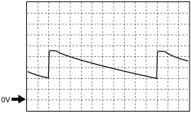
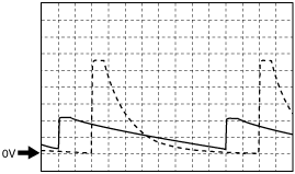
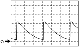
Generated pulse (reference)
Pattern 1
am2zzw00005204
|
Pattern 2
am2zzw00005205
|
Pattern 3
am2zzw00005206
|
Pattern 4
am2zzw00004149
|