ENGINE REMOVAL/INSTALLATION [LF, L5]
id0110a7800400
-
Warning
-
• Fuel vapor is hazardous. It can very easily ignite, causing serious injury and damage. Always keep sparks and flames away from fuel.
• Fuel line spills and leakage are dangerous. Fuel can ignite and cause serious injuries or death and damage. Fuel can also irritate skin and eyes. To prevent this, always complete the “Fuel Line Safety Procedure”. (See
BEFORE SERVICE PRECAUTION [LF, L5].)
• Secure the steering wheel using tape or a cable to prevent the steering shaft from rotating after disconnecting the steering shaft. If the steering wheel rotates after the steering shaft and the steering gear and linkage are disconnected, the internal parts of the clock spring could be damaged.
-
Caution
-
L5
• If the crankshaft and the cylinder block are replaced with a type B from a type A as shown in the figure, perform PCM reprogramming. Otherwise, the engine could be damaged. (See
PCM REPROGRAMMING [LF, L5] .)
Crankshaft
Cylinder block
-
Note
-
• Perform the engine and transaxle component removal/installation from below the vehicle.
1. Remove the battery cover. (See BATTERY REMOVAL/INSTALLATION [LF, L5].)
2. Disconnect the negative battery cable.
3. Remove the plug hole plate. (See PLUG HOLE PLATE REMOVAL/INSTALLATION [LF, L5].)
4. Remove the PCM cover No.1. (See BATTERY REMOVAL/INSTALLATION [LF, L5].)
5. Disconnect the PCM connector. (See PCM REMOVAL/INSTALLATION [LF, L5].)
6. Remove the battery tray and PCM component. (See BATTERY REMOVAL/INSTALLATION [LF, L5].)
7. Remove the air cleaner component. (See INTAKE-AIR SYSTEM REMOVAL/INSTALLATION [LF, L5].)
8. Remove the front wheels and tires. (See GENERAL PROCEDURES (SUSPENSION).)
9. Remove the aerodynamic under cover No.2 and splash shield as a single unit. (See AERODYNAMIC UNDER COVER NO.2 REMOVAL/INSTALLATION.) (See SPLASH SHIELD REMOVAL/INSTALLATION.)
10. Drain the transaxle oil (MTX) or ATF (ATX). (See TRANSAXLE OIL REPLACEMENT [G66M-R] (6MTX).) (See AUTOMATIC TRANSAXLE FLUID (ATF) REPLACEMENT [FS5A-EL] (ATX).)
11. Drain the engine coolant. (See ENGINE COOLANT REPLACEMENT [LF, L5].)
12. Remove the coolant reserve tank. (See COOLANT RESERVE TANK REMOVAL/INSTALLATION [LF, L5].)
13. Disconnect the fuel hose. (See QUICK RELEASE CONNECTOR REMOVAL/INSTALLATION [LF, L5].)
14. Disconnect the evaporative hose. (See QUICK RELEASE CONNECTOR REMOVAL/INSTALLATION [LF, L5].)
15. Disconnect the brake vacuum hose. (See VACUUM HOSE REMOVAL/INSTALLATION [LF, MZR 2.0 DISI i-stop, L5].)
16. Disconnect the radiator hose (upper and lower). (See RADIATOR REMOVAL/INSTALLATION [LF, L5].)
17. Disconnect the water hose. (See THERMOSTAT REMOVAL/INSTALLATION [LF, L5].)
18. Disconnect the heater hose. (See REFRIGERANT LINE REMOVAL/INSTALLATION.)
19. Disconnect the oil hose. (ATX) (See OIL COOLER REMOVAL/INSTALLATION [LF, L5].)
20. Disconnect the power steering pipe component and then drain the power steering fluid. (See GENERAL PROCEDURES (STEERING).)
21. Disconnect the shift cable and wiring harness. (MTX) (See MANUAL TRANSAXLE REMOVAL/INSTALLATION [G66M-R (EXCEPT MZR 2.0 DISI i-stop)].)
22. Remove the clutch release cylinder with the pipe still connected. (MTX) (See CLUTCH RELEASE CYLINDER REMOVAL/INSTALLATION [G66M-R].)
23. Disconnect the selector cable. (ATX) (See AUTOMATIC TRANSAXLE REMOVAL/INSTALLATION [FS5A-EL].)
24. Remove the crossmember bracket. (See FRONT CROSSMEMBER REMOVAL/INSTALLATION [ZY, Z6, LF, L3 Turbo, L5, MZ-CD 1.6 (Y6)].)
25. Set the main silencer out of the way. (LF) (See EXHAUST SYSTEM REMOVAL/INSTALLATION [LF, L5].)
26. Remove the TWC. (L5) (See EXHAUST SYSTEM REMOVAL/INSTALLATION [LF, L5].)
27. Disconnect the drive shafts from the engine side, set the drive shafts out of the way. (See DRIVE SHAFT REMOVAL/INSTALLATION.)
28. Remove the A/C compressor with the cooler hose still connected and secure it using wire or rope so that it is out of the way. (See A/C COMPRESSOR REMOVAL/INSTALLATION.)
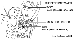
29. Remove the wiring harness installation bolt and nut shown in the figure.
30. Disconnect the ground cable from the No.3 engine mount side.
-
Tightening torque
-
9—12 N·m {92—122 kgf·cm, 80—108 in·lbf}
31. Disconnect the connectors and the wiring harnesses related to the engine removal/installation.
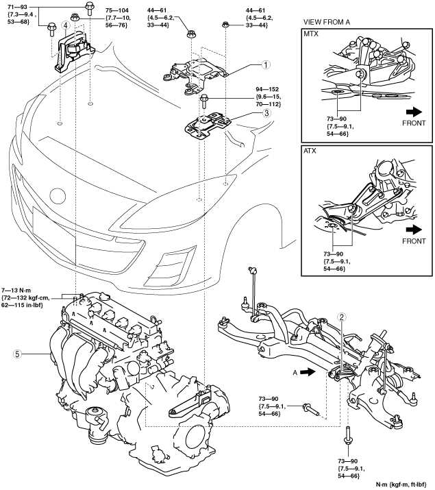
32. Remove in the order indicated in the table.
33. Install in the reverse order of removal.
34. Start the engine. And inspect and adjust the following:
-
• Leakage of engine oil, engine coolant, ATF, transaxle oil, and fuel.
• Runout and contact of pulley and belt.
• Engine-driven accessories operation.
|
1
|
Battery tray bracket
|
|
2
|
No.1 engine mount rubber, front crossmember component
|
|
3
|
No.4 engine mount rubber
|
|
4
|
No.3 engine mount
|
|
5
|
Engine, transaxle
|
No.1 Engine Mount Rubber, Front Crossmember Component Removal Note
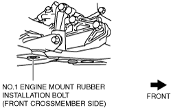
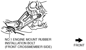
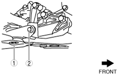
1. Loosen the No.1 engine mount rubber installation bolt (front crossmember side) shown in the figure.
MTX
ATX
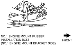
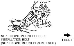
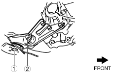
2. Remove the No.1 engine mount rubber installation bolt (No.1 engine mount bracket side) shown in the figure.
MTX
ATX
3. Remove the No.1 engine mount rubber and the front crossmember component as a single unit. (See FRONT CROSSMEMBER REMOVAL/INSTALLATION [ZY, Z6, LF, L3 Turbo, L5, MZ-CD 1.6 (Y6)].)
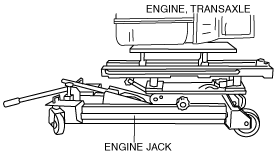
No.3 Engine Mount, No.4 Engine Mount Rubber Removal Note
1. Secure the engine and transaxle using an engine jack.
Engine Mount Installation Note
-
Note
-
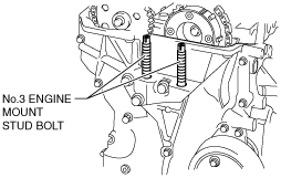
• If the No.3 engine mount bracket and the engine are removed, retighten the No.3 engine mount stud bolts.
1. Tighten the No. 3 engine mount stud bolts.
-
Tightening torque
-
7—13 N·m {72—132 kgf·cm, 62—115 in·lbf}
2. Secure the engine and transaxle using an engine jack.
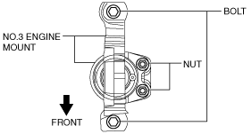
3. Temporarily tighten the No.3 engine mount installation bolts and nuts.
-
Note
-
• Do not tighten the bolts during this step.
4. Temporarily tighten the No.4 engine mount rubber installation bolt as shown in the figure.
5. Install the No.1 engine mount rubber and the front crossmember component as a single unit. (See FRONT CROSSMEMBER REMOVAL/INSTALLATION [ZY, Z6, LF, L3 Turbo, L5, MZ-CD 1.6 (Y6)].)
6. Temporarily tighten the No.1 engine mount rubber installation bolts in the order shown.
-
Caution
-
• Tighten the bolts in the order shown in the figure to prevent abnormal noise and vibration after assembly.
• Tighten the bolts while being careful of their length to prevent interference between the steering gear housing and bolt.
-
Bolt stem length
-
Front crossmember side: 62mm {2.4 in}
No.1 engine mount bracket side: 65mm {2.6 in}
MTX
ATX
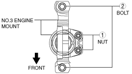
7. Tighten the No.3 engine mount installation bolts and nuts in the order shown in the figure.
|
No.
|
Tightening torque
|
|
1
|
75—104 N·m {7.7—10 kgf·m, 56—76 ft·lbf}
|
|
2
|
71—93 N·m {7.3—9.4 kgf·m, 53—68 ft·lbf}
|
8. Tighten the No.4 engine mount rubber installation bolt.
-
Tightening torque
-
94—152 N·m {9.6—15 kgf·m, 70—112 ft·lbf}
9. Tighten the No.1 engine mount rubber installation bolts in the order shown.
-
Caution
-
• Tighten the bolts in the order shown in the figure to prevent abnormal noise and vibration after assembly.
MTX
ATX
-
Tightening torque
-
73—90 N·m {7.5—9.1 kgf·m, 54—66 ft·lbf}