AUTOMATIC TRANSAXLE REMOVAL/INSTALLATION [FS5A-EL]
id051721294100
-
Caution
-
• Secure the steering wheel using tape or a cable to prevent the steering shaft from rotating after disconnecting the steering shaft. If the steering wheel rotates after the steering shaft and the steering gear and linkage are disconnected, the internal parts of the clock spring could be damaged.
1. Remove the battery cover. (See BATTERY REMOVAL/INSTALLATION [LF, L5].) (See BATTERY REMOVAL/INSTALLATION [MZR 2.0 DISI i-stop].)
2. Disconnect the negative battery cable.
3. Remove the aerodynamic under cover No.2. (See AERODYNAMIC UNDER COVER NO.2 REMOVAL/INSTALLATION.)
4. Remove the front splash shield. (See SPLASH SHIELD REMOVAL/INSTALLATION.)
5. Drain the ATF. (See AUTOMATIC TRANSAXLE FLUID (ATF) REPLACEMENT [FS5A-EL].)
6. Disconnect and/or remove the following parts in the engine compartment.
- (1) Remove the battery. (See BATTERY REMOVAL/INSTALLATION [LF, L5].) (See BATTERY REMOVAL/INSTALLATION [MZR 2.0 DISI i-stop].)
- (2) Remove the battery box. (See BATTERY REMOVAL/INSTALLATION [LF, L5].) (See BATTERY REMOVAL/INSTALLATION [MZR 2.0 DISI i-stop].)
- (3) Remove the battery tray. (See BATTERY REMOVAL/INSTALLATION [LF, L5].) (See BATTERY REMOVAL/INSTALLATION [MZR 2.0 DISI i-stop].)
- (4) Remove the air cleaner component. (See INTAKE-AIR SYSTEM REMOVAL/INSTALLATION [LF, L5].) (See INTAKE-AIR SYSTEM REMOVAL/INSTALLATION [MZR 2.0 DISI i-stop].)
- (5) Remove the exhaust manifold insulator installation bolts and set the exhaust manifold insulator aside. (See EXHAUST SYSTEM REMOVAL/INSTALLATION [LF, L5].) (See EXHAUST SYSTEM REMOVAL/INSTALLATION [MZR 2.0 DISI i-stop].)
- (6) Disconnect the selector cable from the transaxle.
- (7) Remove the insulator from the transaxle.
-
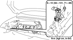
- (8) Disconnect the connectors and GND wiring harness from the transaxle.
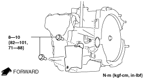
- (9) Remove the bracket from the transaxle.
- (10) Disconnect the oil hoses from the transaxle.
- (11) Remove the water-cooled oil cooler from the transaxle with the hose connected. (See OIL COOLER REMOVAL/INSTALLATION [FS5A-EL].)
- (12) Remove the filler tube from the transaxle.
- (13) Remove the starter. (See STARTER REMOVAL/INSTALLATION [LF, L5].) (See STARTER REMOVAL/INSTALLATION [MZR 2.0 DISI i-stop].)
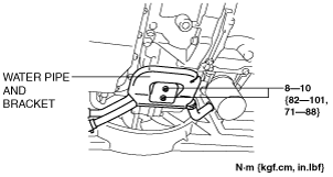
- (14) Disconnect the water pipe and bracket from the electric AT oil pump bracket and set it out of the way. (MZR 2.0 DISI i-stop only)
-
- (15) Remove the electric AT oil pump. (MZR 2.0 DISI i-stop only) (See ELECTRIC AT OIL PUMP REMOVAL/INSTALLATION [FS5A-EL].)
-
-
Caution
-
• Do not drop or apply a shock to the electric AT oil pump. Replace the electric AT oil pump if it has been dropped or received an impact.
- (16) Remove the electric AT oil pump bracket. (MZR 2.0 DISI i-stop only) (See ELECTRIC AT OIL PUMP REMOVAL/INSTALLATION [FS5A-EL].)
7. Disconnect and/or remove the following parts related to the suspension and axle.
- (1) Remove the front tires. (See GENERAL PROCEDURES (FRONT AND REAR AXLES).)
- (2) Disconnect the ABS wheel-speed sensors from the steering knuckles. (See FRONT ABS WHEEL-SPEED SENSOR REMOVAL/INSTALLATION.)
- (3) Disconnect the clip securing the brake hose (LH) from the shock absorber. (See BRAKE HOSE (FRONT) REMOVAL/INSTALLATION [ZY, Z6, LF, MZR 2.0 DISI i-stop, L5, MZ-CD 1.6 (Y6), MZR-CD 2.2].)
- (4) Disconnect the brake hose (LH) from the shock absorber. (See BRAKE HOSE (FRONT) REMOVAL/INSTALLATION [ZY, Z6, LF, MZR 2.0 DISI i-stop, L5, MZ-CD 1.6 (Y6), MZR-CD 2.2].)
- (5) Disconnect the tie-rod end ball joints from the steering knuckles. (See FRONT CROSSMEMBER REMOVAL/INSTALLATION [ZY, Z6, LF, L3 Turbo, L5, MZ-CD 1.6 (Y6)].)
- (6) Disconnect the front lower arms from the steering knuckles. (See FRONT LOWER ARM REMOVAL/INSTALLATION.)
- (7) Disconnect the stabilizer control links from the shock absorbers. (See FRONT SHOCK ABSORBER AND COIL SPRING REMOVAL/INSTALLATION.)
- (8) Disconnect the drive shaft (LH) from the transaxle. (See DRIVE SHAFT REMOVAL/INSTALLATION.)
- (9) Disconnect the drive shaft (RH) from the joint shaft. (See DRIVE SHAFT REMOVAL/INSTALLATION.)
- (10) Disconnect the clips to set the CKP sensor harness out of the way to prevent interference with the joint shaft. (L5).
-
- (11) Remove the joint shaft. (See JOINT SHAFT REMOVAL/INSTALLATION [LF, MZR 2.0 DISI i-stop].) (See JOINT SHAFT REMOVAL/INSTALLATION [ZY, Z6, L3 Turbo, L5].)
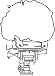
8. Install the SST using the following procedures.
-
Caution
-
• Refer to the SST instruction manual for the basic handing procedure.
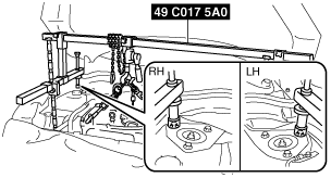
- (1) Remove the installation bolt for the bracket securing the lower radiator hose.
-
- (2) Set the bracket securing the lower radiator hose aside to prevent it from interfering with the front shaft of the SST (right side)
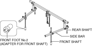
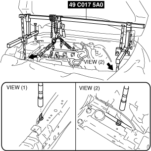
- (3) As shown in the figure, set the rear shafts of the SST to the left and right shock absorber bolts.
-
- (4) Install front foot No.2 to the left/right front shaft of the SST, then align the groove of the front shaft of the SST with the folded up part of the vehicle as shown in the figure.
-
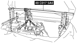
- (5) Adjust the positions of the SST side bars so that they are the same height (left and right) and horizontal. Make sure each joint is securely tightened.
-
- (6) Apply tension to the chain to secure the engine.
9. Remove in the order indicated in the table.
|
1
|
Torque converter installation nuts
|
|
2
|
Transaxle mounting bolts (upper side)
|
|
3
|
Battery tray bracket
|
|
4
|
No.4 engine mount rubber
|
|
5
|
No.4 engine mount bracket
|
|
6
|
No.1 engine mount rubber
|
|
7
|
No.1 engine mount bracket
|
|
8
|
Transaxle mounting bolts (lower side)
|
|
9
|
Transaxle
|
-
Warning
-
• Improperly jacking a transaxle is dangerous. It can slip off the jack and may cause serious injury.
-
Caution
-
• To prevent the torque converter and transaxle from separating, remove the transaxle without tilting it toward the torque converter.
10. Install in the reverse order of removal.
11. Add ATF to the specified level. (See AUTOMATIC TRANSAXLE FLUID (ATF) REPLACEMENT [FS5A-EL].)
12. Perform the following test according to the service item. (See MECHANICAL SYSTEM TEST [FS5A-EL].)(See ROAD TEST [FS5A-EL].)
|
Service item
|
Test item
|
|
Line pressure test
|
Stall test
|
Time lag test
|
Road test
|
|
ATX replacement
|
×
|
|
|
|
|
ATX overhaul
|
×
|
×
|
×
|
×
|
|
Torque converter replacement
|
×
|
×
|
|
|
|
Oil pump replacement
|
×
|
|
|
|
|
Clutch system replacement
|
×
|
|
×
|
×
|
× :Test to be performed after the service work
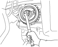
Torque Converter Installation Nuts Removal Note
1. Hold the crankshaft pulley to prevent drive plate from rotating.
2. Remove the torque converter nuts from the starter installation hole.
Transaxle Mounting Bolts (Lower Side) Removal Note
1. Adjust the SST (49 C017 5A0) and lean the engine toward the transaxle.
2. Support the transaxle on a jack.
3. Remove the transaxle mounting bolts (lower side).
4. Remove the transaxle.
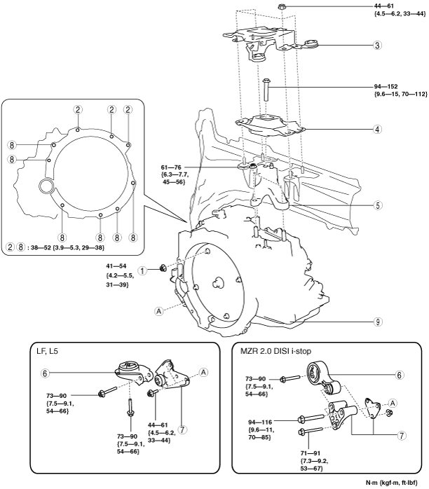
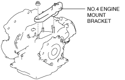
No.1 Engine Mount and No.4 Engine Mount Installation Note (LF, L5)
1. Install the No.4 engine mount bracket to the transaxle case, and then tighten the nuts.
-
Tightening torque
-
61—76 N·m {6.3—7.7 kgf·m, 45—56 ft·lbf}
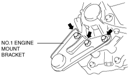
2. Install the No.1 engine mount bracket to the converter housing, and then tighten the bolts.
-
Tightening torque
-
44—61 N·m {4.5—6.2 kgf·m, 33—44 ft·lbf}
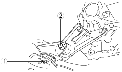
3. Install the No.1 engine mount rubber to the front crossmember, and then temporarily tighten the bolts.
-
Caution
-
• Tighten the bolts while being careful of their length to prevent interference between the steering gear housing and bolt.
-
Bolt stem length
-
Front crossmember side: 62mm {2.4 in}
No.1 engine mount bracket side: 65mm {2.6 in}
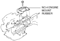
4. Align the No.4 engine mount rubber installation hole to the stud bolts on the body.
5. Install the No.4 engine mount rubber to the No.4 engine mount bracket, and then tighten the bolt.
-
Tightening torque
-
94—152 N·m {9.6—15 kgf·m, 70—112 ft·lbf}
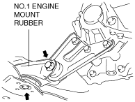
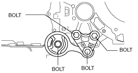
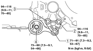
6. Tighten the No.1 engine mount rubber installation bolts in the order shown.
-
Tightening torque
-
73—90 N·m {7.5—9.1 kgf·m, 54—66 ft·lbf}
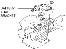
7. Align the battery tray bracket installation hole to the stud bolts on the body.
8. Install the battery tray bracket to the No.4 engine mount rubber, and then tighten the nuts.
-
Tightening torque
-
44—61 N·m {4.5—6.2 kgf·m, 33—44 ft·lbf}
9. Remove the SST (49 C017 5A0).
No.1 Engine Mount and No.4 Engine Mount Installation Note (MZR 2.0 DISI i-stop)
1. Install the No.4 engine mount bracket to the transaxle case, and then tighten the nuts.
-
Tightening torque
-
61—76 N·m {6.3—7.7 kgf·m, 45—56 ft·lbf}
2. Install the No.1 engine mount bracket and the No.1 engine mount rubber the converter housing, and then temporarily tighten the bolts
3. Align the No.4 engine mount rubber installation hole to the stud bolts on the body.
4. Install the No.4 engine mount rubber to the No.4 engine mount bracket, and then tighten the bolt.
-
Tightening torque
-
94—152 N·m {9.6—15 kgf·m, 70—112 ft·lbf}
5. Tighten the No.1 engine mount rubber installation bolts in the order shown.
6. Align the battery tray bracket installation hole to the stud bolts on the body.
7. Install the battery tray bracket to the No.4 engine mount rubber, and then tighten the nuts.
-
Tightening torque
-
44—61 N·m {4.5—6.2 kgf·m, 33—44 ft·lbf}
8. Remove the SST (49 C017 5A0).