 |
am3uuw00005752
BRAKE PEDAL REMOVAL/INSTALLATION [L.H.D.]
id041100801250
1. Remove the battery and battery tray. (except MZR 2.0 DISI i-stop) (See BATTERY REMOVAL/INSTALLATION [ZY, Z6].) (See BATTERY REMOVAL/INSTALLATION [LF, L5].) (See BATTERY REMOVAL/INSTALLATION [L3 Turbo].) (See BATTERY REMOVAL/INSTALLATION [MZ-CD 1.6 (Y6)].) (See BATTERY REMOVAL/INSTALLATION [MZR-CD 2.2].)
2. Remove the main battery, sub battery and battery tray. (MZR 2.0 DISI i-stop) (See BATTERY REMOVAL/INSTALLATION [MZR 2.0 DISI i-stop].)
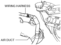
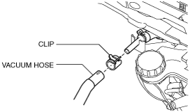
3. Disconnect the vacuum hose from the insulator bracket as shown in the figure. (L3 Turbo)
am3uuw00005752
|
4. Remove the wiring harness from the air duct. (L3 Turbo)
am3uuw00006110
|
5. Remove the dashboard under cover. (If equipped) (See DASHBOARD UNDER COVER REMOVAL/INSTALLATION.)
6. Remove the side wall (driver side). (See SIDE WALL REMOVAL/INSTALLATION.)
7. Disconnect the steering shaft from the steering gear and linkage. (See STEERING WHEEL AND COLUMN REMOVAL/INSTALLATION [WITHOUT ADVANCED KEYLESS ENTRY AND PUSH BUTTON START SYSTEM].) (See STEERING WHEEL AND COLUMN REMOVAL/INSTALLATION [WITH ADVANCED KEYLESS ENTRY AND PUSH BUTTON START SYSTEM].)
8. Remove the accelerator pedal. (See ACCELERATOR PEDAL REMOVAL/INSTALLATION [ZY, Z6].) (See ACCELERATOR PEDAL REMOVAL/INSTALLATION [LF, L5].) (See ACCELERATOR PEDAL REMOVAL/INSTALLATION [MZR 2.0 DISI i-stop].) (See ACCELERATOR PEDAL REMOVAL/INSTALLATION [L3 Turbo].) (See ACCELERATOR PEDAL (APP) REMOVAL/INSTALLATION [MZ-CD 1.6 (Y6)].) (See ACCELERATOR PEDAL COMPONENT REMOVAL/INSTALLATION [MZR-CD 2.2].)
9. Remove in the order indicated in the table.
10. Install in the reverse order of removal.
am3zzw00009596
|
|
1
|
Connector, wiring harness
|
|
2
|
Brake switch
|
|
3
|
Brake pedal position (BPP) switch
|
|
4
|
Joint pin
(See Joint Pin Installation Note.)
|
|
5
|
Nut, bolt
|
|
6
|
Brake pedal
(See Brake Pedal Removal Note.)
|
|
7
|
Pedal pad
|
|
8
|
Bracket
(See Bracket Removal Note.)
(See Bracket Installation Note.)
|
Brake Pedal Removal Note
1. Remove the brake pedal installation bolt and nuts.
2. Move the power brake unit to the vehicle front where the power brake unit fork does not interfere with the brake pedal arm.
3. Remove the brake pedal.
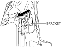
Bracket Removal Note
1. Remove the bracket as shown in the figure.
am3zzw00005712
|
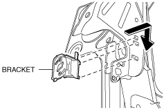
Bracket Installation Note
1. Install the bracket as shown in the figure.
am3zzw00005713
|
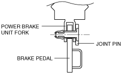
Joint Pin Installation Note
1. Install the new joint pin by aligning the pin holes of the brake pedal and power brake unit fork.
2. Verify that the joint pin touches the power brake unit fork completely.
am3uuw00001795
|
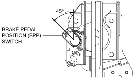
Brake Pedal Position (BPP) Switch Installation Note
1. Inspect the brake pedal. (See BRAKE PEDAL INSPECTION.)
2. With the brake pedal fully released, insert a new brake pedal position (BPP) switch into the installation hole on the brake pedal.
3. Secure the brake pedal position (BPP) switch by turning it clockwise 45°.
am3zzw00005714
|
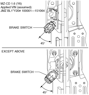
Brake Switch Installation Note
1. Inspect the brake pedal. (See BRAKE PEDAL INSPECTION.)
2. With the brake pedal fully released, insert a new brake switch into the installation hole on the brake pedal.
3. Secure the brake switch by turning it counterclockwise 45°.
am3zzw00009598
|