DTC P2797:00 [FS5A-EL]


id050221824800

DTC P2797:00

Electric AT Oil Pump

DETECTION CONDITION
•  The turbine speed exceeds a certain value several times when returning from i-stop (engine stop control).
Diagnostic support note
•  The MIL does not illuminate.
•  The AT warning light does not illuminate.
•  PENDING CODE is not available.
•  FREEZE FRAME DATA is not available.
•  The DTC is stored in the TCM memory.
POSSIBLE CAUSE
•  ATF deterioration
•  Insufficient ATF level
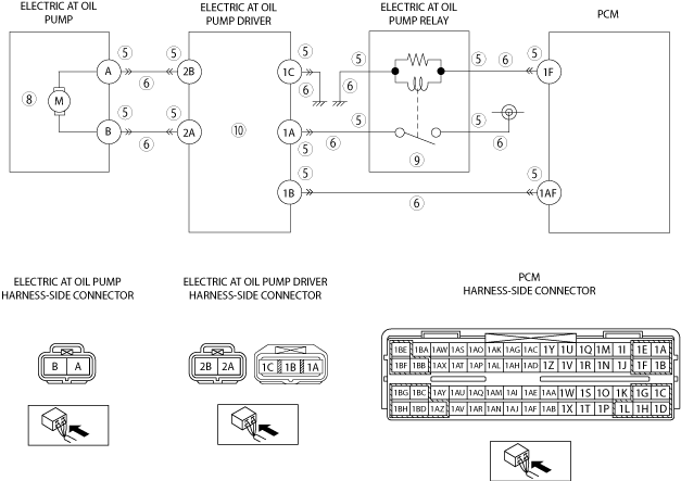
•  Open circuit, or short to ground in wiring harness between PCM terminal 1F and electric AT oil pump relay
•  Open circuit in wiring harness between electric AT oil pump relay and body ground
•  Open circuit, or short to ground in wiring harness between battery and electric AT oil pump relay
•  Open circuit, or short to ground in wiring harness between electric AT oil pump relay and electric AT oil pump driver terminal 1A
•  Open circuit, or short to ground in wiring harness between PCM terminal 1AF and electric AT oil pump driver terminal 1B
•  Open circuit in wiring harness between electric AT oil pump driver terminal 1C and body ground
•  Open circuit, or short to ground in wiring harness between electric AT oil pump terminal A and electric AT oil pump driver terminal 2B
•  Open circuit, or short to ground in wiring harness between electric AT oil pump terminal B and electric AT oil pump driver terminal 2A
•  Connector and terminal malfunctions
•  Line pressure is low
•  Electric AT oil pump malfunction
•  Electric AT oil pump relay malfunction
•  Electric AT oil pump driver malfunction
•  Primary control valve body malfunction
•  TCM malfunction
•  PCM malfunction

Diagnostic procedure

STEP

INSPECTION

ACTION

1
VERIFY RELATED REPAIR INFORMATION AVAILABILITY
•  Verify related Service Information availability.
•  Is any related repair information available?
Yes
Perform repair or diagnosis according to the available repair information.
•  If the vehicle is not repaired, go to the next step.
No
Go to the next step.
2
VERIFY DTCs ARE PRESENT
•  Switch the ignition off, and then switch the ignition to ON (Engine off).
•  Verify the DTCs recorded in the TCM.
•  Are any DTCs other than P2797:00 recorded?
Yes
Go to the applicable DTC inspection.
No
Go to the next step.
3
INSPECT ATF CONDITION
•  Inspect the ATF condition.
•  Is it normal?
Yes
Go to the next step.
No
Replace the ATF, then go to Step 12.
4
INSPECT ATF LEVEL
•  Inspect the ATF level.
•  Is it normal?
Yes
Go to the next step.
No
Add ATF to the specified level, then go to Step 12.
5
INSPECT CONNECTORS FOR POOR CONNECTION
•  Switch the ignition off.
•  Disconnect the following connectors.
―  Electric AT oil pump
―  Electric AT oil pump driver
―  Electric AT oil pump relay
―  PCM
•  Inspect for poor connection (such as damaged/pulled-out pins, corrosion)
•  Is there any malfunction?
Yes
Repair or replace the terminal, then go to Step 12.
No
Go to the next step.
6
INSPECT WIRING HARNESS
•  Inspect the wiring harness between the PCM terminal 1F and electric AT oil pump relay for an open or short circuit.
•  Inspect the wiring harness between the electric AT oil pump relay and body ground for an open circuit.
•  Inspect the wiring harness between the battery and electric AT oil pump relay for an open or short circuit.
•  Inspect the wiring harness between the electric AT oil pump relay and electric AT oil pump driver terminal 1A for an open or short circuit.
•  Inspect the wiring harness between the PCM terminal 1AF and electric AT oil pump driver terminal 1B for an open or short circuit.
•  Inspect the wiring harness between the electric AT oil pump driver terminal 1C and body ground for an open circuit.
•  Inspect the wiring harness between the electric AT oil pump terminal A and electric AT oil pump driver terminal 2B for an open or short circuit.
•  Inspect the wiring harness between the electric AT oil pump terminal B and electric AT oil pump driver terminal 2A for an open or short circuit.
•  Is the wiring harness normal?
Yes
Go to the next step.
No
Repair or replace the malfunctioning wiring harness, then go to Step 12.
7
INSPECT LINE PRESSURE
•  Perform the “Line Pressures Test”.
•  Is there any malfunction?
Yes
Repair or replace malfunctioning part according to test result, then go to Step 12.
No
Go to the next step.
8
INSPECT ELECTRIC AT OIL PUMP
•  Inspect the electric AT oil pump.
•  Is the electric AT oil pump normal?
Yes
Go to the next step.
No
Replace the electric AT oil pump, then go to Step 12.
9
INSPECT ELECTRIC AT OIL PUMP RELAY
•  Inspect the electric AT oil pump relay.
•  Is the electric AT oil pump relay normal?
Yes
Go to the next step.
No
Replace the electric AT oil pump relay, then go to Step 12.
10
INSPECT ELECTRIC AT OIL PUMP DRIVER
•  Inspect the electric AT oil pump driver.
•  Is the electric AT oil pump driver normal?
Yes
Go to the next step.
No
Replace the electric AT oil pump driver, then go to Step 12.
11
INSPECT PRIMARY CONTROL VALVE BODY
•  Remove the primary control valve body.
•  Disassemble the primary control valve body.
•  Inspect the following parts:
―  Shift valve condition
―  Return spring condition
―  Clogging in oil passage
•  Is there any malfunction?
Yes
Repair or replace malfunctioning part according to inspection result, then go to next step.
No
Replace the transaxle, then go to the next step.
12
VERIFY DTC TROUBLESHOOTING COMPLETED
•  Make sure to reconnect all the disconnected connectors.
•  Clear the DTC using the M-MDS.
•  Perform the following procedure to ensure that the DTC has been resolved:
1.  Operate i-stop more than 10 times.
•  Is the same DTC present?
Yes
Replace the TCM or PCM, then go to the next step.
No
Go to the next step.
13
VERIFY NO DTCs ARE PRESENT
•  Perform the “Reading DTCs Procedure”.
•  Are any DTCs present?
Yes
Go to the applicable DTC inspection.
No
DTC troubleshooting completed.