 |
am3zzw00006428
FUEL GAUGE SENDER UNIT REMOVAL/INSTALLATION
id092200801900
Except MZ-CD 1.6 (Y6), MZR-CD 2.2
MZ-CD 1.6 (Y6)
1. Level the vehicle.
2. Complete the “BEFORE SERVICE PRECAUTION”. (See BEFORE SERVICE PRECAUTION [MZ-CD 1.6 (Y6)].)
3. Disconnect the negative battery cable. (See BATTERY REMOVAL/INSTALLATION [MZ-CD 1.6 (Y6)].)
4. Drain the fuel using the following procedure.
5. Remove the rear seat cushion. (See REAR SEAT CUSHION REMOVAL/INSTALLATION.)
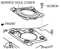
6. Remove the service hole cover.
am3zzw00006428
|
7. Disconnect the fuel gauge sender unit connector.
8. Set the main silencer out of the way. (See EXHAUST SYSTEM REMOVAL/INSTALLATION [MZ-CD 1.6 (Y6)].)
9. Remove the insulator (middle No.1). (See EXHAUST SYSTEM REMOVAL/INSTALLATION [MZ-CD 1.6 (Y6)].)
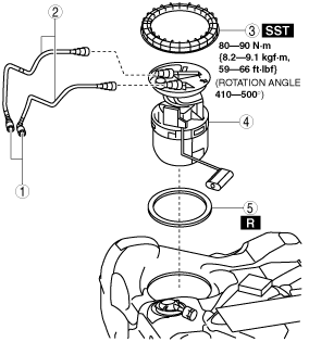
10. Remove in the order indicated in the table.
am3zzw00009767
|
|
1
|
Quick release connector
|
|
2
|
Fuel hose
(See Fuel Hose Removal Note.)
|
|
3
|
Fuel gauge sender unit cap
(See Fuel Pump Cap Removal Note.)
|
|
4
|
Fuel gauge sender unit
|
|
5
|
O-ring
|
11. Install in the reverse order of removal.
12. Complete the “AFTER SERVICE PRECAUTION”. (See AFTER SERVICE PRECAUTION [MZ-CD 1.6 (Y6)].)
Fuel Hose Removal Note
1. Remove the fuel-filler pipe installation bolts. (See FUEL TANK REMOVAL/INSTALLATION [MZ-CD 1.6 (Y6)].)
2. Disconnect the joint hose of fuel tank side. (See FUEL TANK REMOVAL/INSTALLATION [MZ-CD 1.6 (Y6)].)
3. Disconnect the breather hose of fuel-filler pipe side. (See FUEL TANK REMOVAL/INSTALLATION [MZ-CD 1.6 (Y6)].)
4. Remove the fuel tank strap. (See FUEL TANK REMOVAL/INSTALLATION [MZ-CD 1.6 (Y6)].)
5. Remove the following parts as a single unit.
6. Remove the fuel hose.
Fuel Pump Cap Removal Note
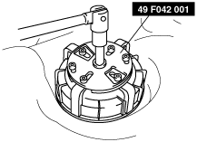
1. Remove the fuel pump cap using the SST.
am3zzw00001758
|
Fuel Pump Cap Installation Note
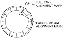
1. Align the fuel tank and fuel pump unit alignment marks.
am3zzw00001759
|
2. Set the SST as shown in the figure.
am3zzw00001758
|
3. Using the SST, tighten the fuel pump cap within the specified tightening torque without shifting the alignment marks.
MZR-CD 2.2
1. Level the vehicle.
2. Complete the “BEFORE SERVICE PRECAUTION”. (See BEFORE SERVICE PRECAUTION [MZR-CD 2.2].)
3. Disconnect the negative battery cable. (See BATTERY REMOVAL/INSTALLATION [MZR-CD 2.2].)
4. Drain the fuel using the following procedure.
5. Remove the rear seat cushion. (See REAR SEAT CUSHION REMOVAL/INSTALLATION.)
6. Remove the service hole cover.
am3zzw00006428
|
7. Disconnect the fuel gauge sender unit connector.
8. Set the presilencer out of the way. (See EXHAUST SYSTEM REMOVAL/INSTALLATION [MZR-CD 2.2].)
9. Remove the insulator (middle No.1). (See EXHAUST SYSTEM REMOVAL/INSTALLATION [MZR-CD 2.2].)
10. Remove in the order indicated in the table.
am3zzw00009768
|
|
1
|
Quick release connector
|
|
2
|
Fuel hose
(See Fuel Hose Removal Note.)
|
|
3
|
Fuel gauge sender unit cap
(See Fuel Pump Cap Removal Note.)
|
|
4
|
Fuel gauge sender unit
|
|
5
|
O-ring
|
11. Install in the reverse order of removal.
12. Complete the “AFTER SERVICE PRECAUTION”. (See AFTER SERVICE PRECAUTION [MZR-CD 2.2].)
Fuel Hose Removal Note
1. Remove the fuel-filler pipe installation bolts. (See FUEL TANK REMOVAL/INSTALLATION [MZR-CD 2.2].)
2. Disconnect the joint hose of fuel tank side. (See FUEL TANK REMOVAL/INSTALLATION [MZR-CD 2.2].)
3. Disconnect the breather hose of fuel-filler pipe side. (See FUEL TANK REMOVAL/INSTALLATION [MZR-CD 2.2].)
4. Remove the fuel tank strap. (See FUEL TANK REMOVAL/INSTALLATION [MZR-CD 2.2].)
5. Remove the following parts as a single unit.
6. Remove the fuel hose. (See QUICK RELEASE CONNECTOR REMOVAL/INSTALLATION [MZR-CD 2.2].)
Fuel Pump Cap Removal Note
1. Remove the fuel pump cap using the SST.
am3zzw00001758
|
Fuel Pump Cap Installation Note
1. Align the fuel tank and fuel pump unit alignment marks.
am3zzw00001759
|
2. Set the SST as shown in the figure.
am3zzw00001758
|
3. Using the SST, tighten the fuel pump cap within the specified tightening torque without shifting the alignment marks.