 |
am3zzw00004520
ENGINE REMOVAL/INSTALLATION [L3 Turbo]
id0110b3800400
1. Remove the battery and battery tray. (See BATTERY REMOVAL/INSTALLATION [L3 Turbo].)
2. Remove the front tire.
3. Remove the charge air cooler cover. (See INTAKE-AIR SYSTEM REMOVAL/INSTALLATION [L3 Turbo].)
4. Remove the air cleaner. (See INTAKE-AIR SYSTEM REMOVAL/INSTALLATION [L3 Turbo].)
5. Remove the under cover, splash shield and mudguard.
6. Drain the engine coolant (See ENGINE COOLANT REPLACEMENT [L3 Turbo].)
7. Drain the transaxle oil. (See TRANSAXLE OIL REPLACEMENT [A26M-R].)
8. Remove the drive belt. (See DRIVE BELT REMOVAL/INSTALLATION [L3 Turbo].)
9. Remove the tunnel member. (See EXHAUST SYSTEM REMOVAL/INSTALLATION [L3 Turbo].)
10. Remove the member. (See EXHAUST SYSTEM REMOVAL/INSTALLATION [L3 Turbo].)
11. Remove the TWC. (See EXHAUST SYSTEM REMOVAL/INSTALLATION [L3 Turbo].)
12. Remove the insulator. (See EXHAUST SYSTEM REMOVAL/INSTALLATION [L3 Turbo].)
13. Remove the WU-TWC. (See EXHAUST SYSTEM REMOVAL/INSTALLATION [L3 Turbo].)
14. Disconnect the heater hose. (See A/C UNIT REMOVAL/INSTALLATION.)
15. Disconnect the radiator hose. (See RADIATOR REMOVAL/INSTALLATION [L3 Turbo].)
16. Disconnect the brake vacuum hose. (See VACUUM HOSE REMOVAL/INSTALLATION [ZJ, ZY, Z6, LF, L3, L3 Turbo].)
17. Disconnect the fuel hose and vacuum hose. (See QUICK RELEASE CONNECTOR REMOVAL/INSTALLATION [L3 Turbo].)
18. Disconnect the shift cable. (See MANUAL TRANSAXLE REMOVAL/INSTALLATION [A26M-R].)
19. Disconnect the clutch release cylinder with the pipe. (See CLUTCH RELEASE CYLINDER REMOVAL/INSTALLATION [F35M-R, G35M-R, G66M-R, A26M-R].)
20. Disconnect the wiring harnesses.
21. Disconnect the front drive shaft (RH) from the joint shaft side. (See DRIVE SHAFT REMOVAL/INSTALLATION.)
22. Disconnect the front drive shaft (LH) from the transaxle side. (See DRIVE SHAFT REMOVAL/INSTALLATION.)
23. Remove the A/C compressor with the pipes still connected. (See A/C COMPRESSOR REMOVAL/INSTALLATION [L3 Turbo].)
24. Remove the front crossmember, lower arm, front stabilizer, and steering gear and linkage as a single unit. (See FRONT CROSSMEMBER REMOVAL/INSTALLATION.)
25. Remove in the order indicated in the figure.
26. Install in the reverse order of removal.
27. Start the engine, and inspect and adjust the following:
28. Perform a road test and verify that there is no abnormal vibration or noise.
am3zzw00004520
|
|
1
|
Main fuse block connector
|
|
2
|
No.1 engine mount rubber
|
|
3
|
No.3 Engine mount
|
|
4
|
Dynamic damper (if equipped)
|
|
5
|
Battery bracket
|
|
6
|
No.4 Engine mount rubber
|
|
7
|
Engine, transaxle
|
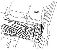
Main Fuse Block Connector Removal Note
1. Release the tab in the order shown in the figure.
am3zzw00002473
|
2. Pull the lock lever up and remove the connector.
No.3 Engine Mount and No.4 Engine Mount Rubber Removal Note
1. Secure the engine and the transaxle using an engine jack and attachment as shown in the figure.
am3zzw00002474
|
No.3 Engine Mount and No.4 Engine Mount Rubber Installation Note
1. Secure the engine and the transaxle using an engine jack and attachment as shown in the figure.
am3zzw00002474
|
2. Install the No.1 engine mount rubber and No.4 engine mount rubber.
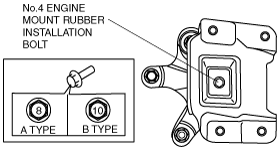
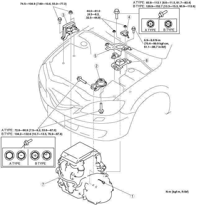
3. Tighten the new No.4 engine mount rubber installation bolt as shown in the figure.
am3uuw00001177
|
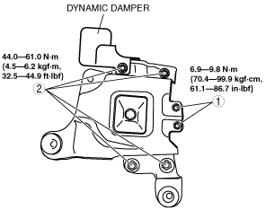
4. Tighten the No.4 engine mount rubber and battery bracket bolts and nuts in the order as shown in the figure.
am3zzw00002476
|
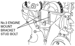
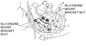
5. Tighten the No.3 engine mount bracket stud bolts.
am3zzw00002477
|
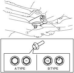
6. Tighten the No.3 engine mount bracket bolts and nuts in the order as shown in the figure.
am3zzw00002478
|
No.1 Engine Mount Rubber Installation Note
1. Remove the engine jack and attachment.
2. Tighten the No.1 engine mount rubber installation bolts as shown in the figure.
am3zzw00009593
|