 |
am3zzw00003345
PID/DATA MONITOR INSPECTION [FS5A-EL]
id050221805600
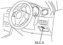
1. Connect the M-MDS to the DLC-2.
am3zzw00003345
|
2. After the vehicle is identified, select the following items from the initial screen of the M-MDS.
3. Select the PID from the PID table
4. Verify the PID data according to the directions on the M-MDS screen.
PID/DATA MONITOR AND RECORD function table
|
Monitor item (Definition) |
Unit/Condition |
Condition/Specification |
Action |
TCM terminal |
|
|---|---|---|---|---|---|
|
DTCCNT
(Number of DTC detected)
|
N/A
|
• DTCs is detected: 1—255
• No DTCs are detected: 0
|
Perform applicable DTC troubleshooting.
(See DTC TABLE [FS5A-EL].)
|
N/A
|
|
|
DWN SW
(Down switch)
|
On/Off
|
• M range, downshift: On
• Other: Off
|
Inspect the selector lever component.
|
F
|
|
|
ECT TCM
(ECT sensor)
|
°C
|
°F
|
Indicates engine coolant temperature
|
Inspect the ECT sensor.
Inspect the PCM
(See PCM INSPECTION [LF, L3].)
|
N/A
|
|
GEAR_SEL
|
1/2/3/4/5
|
• 1GR: 1
• 2GR: 2
• 3GR: 3
• 4GR: 4
• 5GR: 5
|
Inspect the following PIDs:
SSA/SS1, SSB/SS2, SSC/SS3,
SSD/SS4, SSE_SS5, SSF_SS6
|
N/A
|
|
|
HTM_CNT
|
N/A
|
Indicates number of high oil temperature mode (ATF temperature at 130 °C {266 °F} or more) operations
• 0—65,535
|
N/A
|
N/A
|
|
|
HTM_DIS
|
km
|
Indicates travel distance after operation of high oil temperature mode (ATF temperature at 130 °C {266 °F} or more)
• 0—65,535 km
|
N/A
|
N/A
|
|
|
ISS
(Intermediate shaft speed)
|
RPM
|
Indicates secondary gear revolution speed
• Vehicle speed 0 km/h {0 mph}: 0 RPM
• Vehicle speed 25 km/h {16 mph}: 200—230 RPM
|
Inspect the intermediate sensor.
|
AC
|
|
|
LINEDES
|
kPa
|
inHg
|
Indicates target line pressure
|
Inspect the following PIDs:
ISS, OSS, TFT, TFTV, THOP, TR, TSS
|
N/A
|
|
LPS
(Pressure control solenoid A)
|
A
|
Change current value according to throttle opening angle
|
Inspect the pressure control solenoid A.
|
AD, AE
|
|
|
LPS B
(Pressure control solenoid B)
|
%
|
• 4GR→ 5GR: 99%
• others: 0%
|
Inspect the pressure control solenoid B.
|
AM
|
|
|
MNL SW
(M range switch)
|
On/Off
|
• M range: On
• Other: Off
|
Inspect the selector lever component.
|
K
|
|
|
OP_SW_B
(Oil pressure switch)
|
On/Off
|
• 1GR, 2GR or 3GR: On
• Other: Off
|
Inspect the oil pressure switch.
|
S
|
|
|
OSS
(Output shaft speed)
|
RPM
|
Indicates output shaft speed
• Vehicle speed 0 km/h {0 mph}: 0 RPM
• Vehicle speed 25 km/h {16 mph}: 200—230 RPM
|
Inspect the VSS.
|
Z
|
|
|
RPM_TCM
(Engine speed)
|
RPM
|
Ignition switch ON: 0 RPM
Idle: 700—800 RPM
|
Inspect the TCM.
(See TCM INSPECTION [FS5A-EL].)
|
N/A
|
|
|
SSA/SS1
(Shift solenoid A)
|
%
|
• 4GR: 99%
• others: 0%
|
Inspect the shift solenoid A.
|
AG
|
|
|
SSB/SS2
(Shift solenoid B)
|
%
|
• 1GR at D range: 99%
• Others: 0%
|
Inspect the shift solenoid B.
|
AJ
|
|
|
SSC/SS3
(Shift solenoid C)
|
%
|
• 1GR/2GR: 99%
• Others: 0%
|
Inspect the shift solenoid C.
|
AL
|
|
|
SSD/SS4
(Shift solenoid D)
|
On/Off
|
• P/N position, 4GR at D range, 1GR at M range: On
• Others: Off
|
Inspect the shift solenoid D.
|
AH
|
|
|
SSE_SS5
(Shift solenoid E)
|
On/Off
|
• TCC operating: On
• TCC non operating: Off
|
Inspect the shift solenoid E.
|
AK
|
|
|
SSF_SS6
(Shift solenoid F)
|
On/Off
|
• 1GR/2GR/3GR/4GR: On
• 5GR: Off
|
Inspect the shift solenoid F.
|
AI
|
|
|
TFT
(Transaxle fluid temperature)
|
°C
|
°F
|
Indicates transaxle fluid temperature
|
Inspect the TFT sensor.
|
AA
|
|
TFTV
(Transaxle fluid signal voltage)
|
V
|
• ATF 20 °C {68 °F}: Approx. 3.3 V
• ATF 40 °C {104 °F}: Approx. 2.4 V
• ATF 60 °C {140 °F}: Approx. 1.5 V
|
Inspect the TFT sensor.
|
AA
|
|
|
THOP
(Throttle position sensor)
|
%
|
• Accelerator pedal released: 0%
• Accelerator pedal fully depressed: 100%
|
Inspect the APP sensor.
|
N/A
|
|
|
TR
(Transaxle range)
|
P/R/N/D
|
• P position: P
• R position: R
• N position: N
• D range: D
|
Inspect the TR switch.
|
U
|
|
|
TR_SENS
(TR switch)
|
V
|
• P position: 4.34—4.79 V
• R position: 3.83—4.18 V
• N position: 3.05—3.50 V
• D range: 2.23—2.66 V
|
Inspect the TR switch.
|
U
|
|
|
TSS
(Input/turbine speed)
|
RPM
|
Indicates Input/turbine speed
• Ignition switch ON: 0 RPM
• Idle: 700—800 RPM (P, N position)
|
Inspect the input/turbine speed sensor.
|
Y, AB
|
|
|
UP SW
(Up switch)
|
On/Off
|
• M range, upshift: On
• Other: Off
|
Inspect the selector lever component.
|
G
|
|
|
VPWR_TCM
(Battery voltage)
|
V
|
B+
|
Inspect the main relay.
(See RELAY INSPECTION.)
|
J
|
|
|
VSS
(Vehicle speed)
|
KPH
|
• Vehicle speed 20 km/h {12.5 mph}: 20 KPH
• Vehicle speed 40 km/h {25 mph}: 40 KPH
|
Inspect the VSS.
|
Z
|
|
Simulation Function Procedure
1. Connect the M-MDS to the DLC-2.
am3zzw00003345
|
2. After the vehicle is identified, select the following items from the initial screen of the M-MDS.
3. Select the simulation items from the PID table.
4. Perform the simulation function, inspect the operations for each parts.
Simulation item table
|
Simulation item |
Applicable component |
Unit/Condition |
Operation |
TCM terminal |
|
|---|---|---|---|---|---|
|
IG ON |
Idle |
||||
|
LPS
|
Pressure control solenoid A
|
%
|
N/A
|
X
|
AD, AE
|
|
LPS B
|
Pressure control solenoid B
|
%
|
N/A
|
X
|
AM
|
|
SSA/SS1
|
Shift solenoid A
|
%
|
N/A
|
X
|
AG
|
|
SSB/SS2
|
Shift solenoid B
|
%
|
N/A
|
X
|
AJ
|
|
SSC/SS3
|
Shift solenoid C
|
%
|
N/A
|
X
|
AL
|
|
SSD/SS4
|
Shift solenoid D
|
On/Off
|
N/A
|
X
|
AH
|
|
SSE_SS5
|
Shift solenoid E
|
On/Off
|
N/A
|
X
|
AK
|
|
SSF_SS6
|
Shift solenoid F
|
On/Off
|
N/A
|
X
|
AI
|