|
1
|
VERIFY FREEZE FRAME DATA HAS BEEN RECORDED
• Has the FREEZE FRAME DATA been recorded?
|
Yes
|
Go to the next step.
|
|
No
|
Record the FREEZE FRAME DATA on the repair order, then go to the next step.
|
|
2
|
VERIFY RELATED SERVICE INFORMATION AVAILABILITY
• Verify related Service Information availability.
• Is any related Service Information available?
|
Yes
|
Perform repair or diagnosis according to the available Service Information.
• If the vehicle is not repaired, go to the next step.
|
|
No
|
Go to the next step.
|
|
3
|
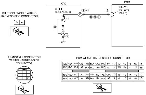
INSPECT ATX CONNECTOR FOR POOR CONNECTION
• Turn the ignition switch to the LOCK position.
• Disconnect the ATX connector.
• Inspect for poor connection (such as damaged/pulled-out pins, corrosion).
• Is the connection normal?
|
Yes
|
Go to the next step.
|
|
No
|
Repair or replace the connector and/or terminals, then go to Step 11.
|
|
4
|
INSPECT RESISTANCE
• Inspect the resistance between ATX terminal C (transaxle case side) and body ground.
• Is the resistance within 1.0—4.2 ohms?
|
Yes
|
Go to Step 7.
|
|
No
|
Go to the next step.
|
|
5
|
INSPECT SHIFT SOLENOID B CONNECTOR FOR POOR CONNECTION
• Disconnect the shift solenoid B connector.
• Inspect for poor connection (such as damaged/pulled-out pins, corrosion).
• Is the connection normal?
|
Yes
|
Go to the next step.
|
|
No
|
Repair or replace the connector and/or terminals, then go to Step 11.
|
|
6
|
INSPECT RESISTANCE
• Inspect the resistance between shift solenoid B terminals A and B (part-side).
• Is the resistance within 1.0—4.2 ohms?
|
Yes
|
Replace the solenoid wiring harness, then go to Step 11.
|
|
No
|
Verify shift solenoid B installation.
• If solenoid installed correctly, replace the solenoid, then go to Step 11.
|
|
7
|
INSPECT PCM CONNECTOR FOR POOR CONNECTION
• Disconnect the PCM connector.
• Inspect for poor connection (such as damaged/pulled-out pins, corrosion).
• Is the connection normal?
|
Yes
|
Go to the next step.
|
|
No
|
Repair or replace the connector and/or terminals, then go to Step 11.
|
|
8
|
INSPECT ATX CONNECTOR CIRCUIT FOR OPEN CIRCUIT
• Inspect for continuity between PCM terminal 1H (ZY)/1BH (Z6)/1C (LF) (wiring harness-side) and ATX terminal C (wiring harness-side).
• Is there continuity between terminals?
|
Yes
|
Go to the next step.
|
|
No
|
Repair or replace the wiring harness, then go to Step 11.
|
|
9
|
INSPECT ATX CONNECTOR CIRCUIT FOR SHORT TO POWER SUPPLY
• Turn the ignition switch to the ON position (engine off).
• Inspect for voltage at ATX terminal C (wiring harness-side).
• Is the voltage 0 V?
|
Yes
|
Go to the next step.
|
|
No
|
Repair or replace the wiring harness, then go to Step 11.
|
|
10
|
INSPECT PCM CIRCUIT FOR SHORT TO GROUND
• Turn the ignition switch to the LOCK position.
• Inspect for continuity between PCM terminal 1H (ZY)/1BH (Z6)/1C (LF) (wiring harness-side) and body ground.
• Is there continuity?
|
Yes
|
Repair or replace the wiring harness, then go to Step 11.
|
|
No
|
Go to the next step.
|
|
11
|
VERIFY TROUBLESHOOTING OF DTC P0758 SHIFT SOLENOID B COMPLETED
• Make sure to reconnect all the disconnected connectors.
• Clear the DTC from the memory using the M-MDS.
• Drive the vehicle in D range and make sure that the gears shift smoothly from 1GR to 4GR.
• Are any DTCs present?
|
Yes
|
Replace the PCM, then go to the next step.
|
|
No
|
Go to the next step.
|
|
12
|
VERIFY AFTER REPAIR PROCEDURE
• Perform the "After Repair Procedure".
• Are any DTCs present?
|
Yes
|
Go to the applicable DTC inspection.
|
|
No
|
DTC troubleshooting completed.
|