 |
am3zzw00020551
FRONT FENDER STAY REMOVAL/INSTALLATION
id091000803900
Front Fender Stay (LH)
1. Disconnect the negative battery cable. (See NEGATIVE BATTERY CABLE DISCONNECTION/CONNECTION [SKYACTIV-G 1.5, SKYACTIV-G 2.0, SKYACTIV-G 2.5].) (See NEGATIVE BATTERY CABLE DISCONNECTION/CONNECTION [MZR 1.6].) (See NEGATIVE BATTERY CABLE DISCONNECTION/CONNECTION [SKYACTIV-D 2.2].) (See NEGATIVE BATTERY CABLE DISCONNECTION/CONNECTION [SKYACTIV-D 1.5].)
2. Remove the following parts:
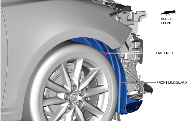
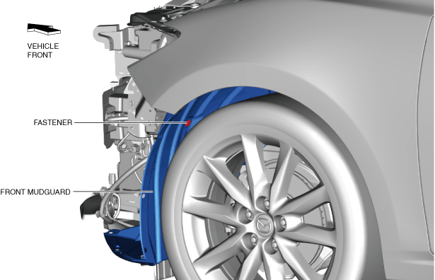
3. Remove the fastener.
am3zzw00020551
|
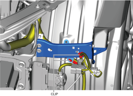
4. Remove the wiring harness clips.
am3zzw00018772
|
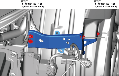
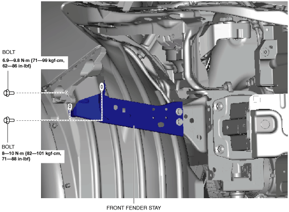
5. Remove the bolts shown in the figure.
am3zzw00018773
|
6. Install in the reverse order of removal. (See Front Fender Stay Newly Replace Note.)
7. Adjust the headlight aiming. (See HEADLIGHT AIMING.)
Front Fender Stay (RH)
1. Disconnect the negative battery cable. (See NEGATIVE BATTERY CABLE DISCONNECTION/CONNECTION [SKYACTIV-G 1.5, SKYACTIV-G 2.0, SKYACTIV-G 2.5].) (See NEGATIVE BATTERY CABLE DISCONNECTION/CONNECTION [MZR 1.6].) (See NEGATIVE BATTERY CABLE DISCONNECTION/CONNECTION [SKYACTIV-D 2.2].) (See NEGATIVE BATTERY CABLE DISCONNECTION/CONNECTION [SKYACTIV-D 1.5].)
2. Remove the following parts:
3. Remove the fastener.
am3zzw00020552
|
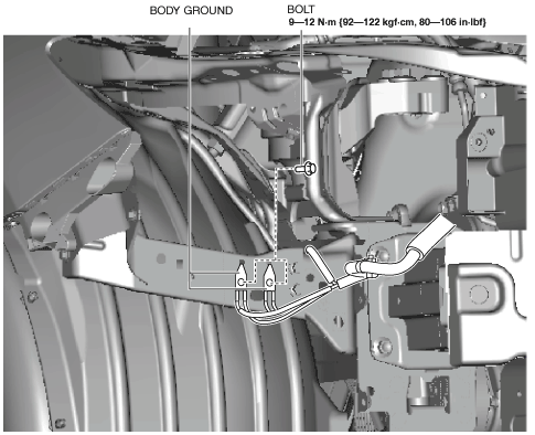
4. Remove the bolt shown in the figure and then remove body ground.
SKYACTIV-G 1.5, SKYACTIV-G 2.0, SKYACTIV-G 2.5, MZR 1.6
am3uuw00011636
|
SKYACTIV-D 1.5, SKYACTIV-D 2.2
am3zzw00014328
|
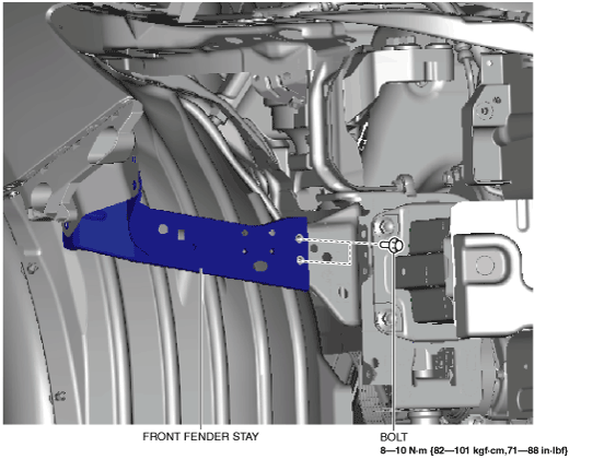
5. Remove the bolts shown in the figure.
am3uuw00011637
|
6. Remove the bolts shown in the figure and then remove the front fender stay.
am3uuw00011638
|
7. Install in the reverse order of removal. (See Front Fender Stay Newly Replace Note.)
8. Adjust the headlight aiming. (See HEADLIGHT AIMING.)
Front Fender Stay Newly Replace Note