 |
bfw2za00000397
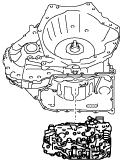
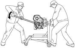
AUTOMATIC TRANSAXLE DISASSEMBLY [EW6A-EL/EW6AX-EL]
id0517006606l4
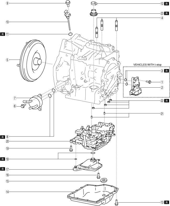
Structural View
Automatic transaxle 1
bfw2za00000397
|
|
1
|
3 bolts (Vehicles with i-stop)
|
|
2
|
Electric AT oil pump (Vehicles with i-stop)
|
|
3
|
O-ring (Vehicles with i-stop)
|
|
4
|
Stud bolt
|
|
5
|
Torque converter
|
|
6
|
3 bolts
|
|
7
|
Oil cooler
|
|
8
|
O-ring
|
|
9
|
Bolt
|
|
10
|
Dipstick
|
|
11
|
O-ring
|
|
12
|
Hose clamp
|
|
13
|
16 bolts
|
|
14
|
Oil pan
|
|
15
|
Magnet
|
|
16
|
2 bolts
|
|
17
|
Oil strainer
|
|
18
|
O-rings
|
|
19
|
11 bolts
|
|
20
|
Control valve body
|
|
21
|
Dowel pin
|
|
22
|
Gasket
|
|
23
|
Oil seal
|
Automatic transaxle 2
bfw2za00000398
|
|
1
|
25 bolts
|
|
2
|
Converter housing
|
|
3
|
O-ring
|
|
4
|
O-ring
|
|
5
|
2 bolts
|
|
6
|
Baffle plate
|
|
7
|
Oil seal
|
|
8
|
Bearing race
|
|
9
|
Shim
|
|
10
|
Bearing race
|
|
11
|
Shim
|
|
12
|
Service hole cover (With service hole cover)
|
Automatic transaxle 3
bfw2za00000399
|
|
1
|
Baffle plate
|
|
2
|
7 bolts
|
|
3
|
Oil pump
|
|
4
|
Thrust needle bearing
|
|
5
|
High clutch component and low clutch component
|
|
6
|
Turbine shaft
|
|
7
|
D-ring
|
|
8
|
Seal ring
|
|
9
|
Thrust needle bearing
|
|
10
|
High clutch hub
|
|
11
|
Thrust needle bearing
|
|
12
|
Low clutch hub
|
|
13
|
Thrust needle bearing
|
|
14
|
Ring gear and differential
|
|
15
|
Oil pipe
|
|
16
|
Secondary gear and output gear
|
|
17
|
2 bolts
|
|
18
|
Baffle plate
|
|
19
|
Oil seal
|
|
20
|
Tapered roller bearing
|
|
21
|
Bearing race
|
Automatic transaxle 4
bfw2za00001202
|
|
1
|
12 bolts
|
|
2
|
End cover component
|
|
3
|
O-ring
|
|
4
|
Shim
|
|
5
|
Thrust needle bearing
|
|
6
|
Reduction sun gear
|
|
7
|
Thrust needle bearing
|
|
8
|
Rear planetary gear
|
|
9
|
Rear sun gear
|
|
10
|
Front sun gear
|
|
11
|
Locknut
|
|
12
|
Front planetary gear
|
|
13
|
Snap ring
|
|
14
|
One-way clutch
|
|
15
|
Drive plate
|
|
16
|
Driven plate
|
|
17
|
Springs and retainer component
|
|
18
|
Low and reverse brake piston
|
Automatic transaxle 5
bfw2za00000401
|
|
1
|
Connector
|
|
2
|
Gasket
|
|
3
|
Gasket
|
|
4
|
Oil pipe
|
|
5
|
O-ring
|
|
6
|
2 bolts
|
|
7
|
Detent bracket component
|
|
8
|
Pawl return spring
|
|
9
|
Support actuator
|
|
10
|
Parking pawl pin
|
|
11
|
Parking rod component
|
|
12
|
Plug
|
|
13
|
Gasket
|
|
14
|
Parking pawl shaft
|
|
15
|
Parking pawl
|
|
16
|
Roll pin
|
|
17
|
Parking shift lever component
|
|
18
|
Parking assist lever component
|
|
19
|
Manual plate component
|
|
20
|
Oil seal
|
|
21
|
Washer
|
Automatic transaxle 6
bfw2za00000402
|
|
1
|
Primary gear
|
|
2
|
Angular contact ball bearing
|
|
3
|
Plug
|
|
4
|
Gasket
|
|
5
|
Transaxle case
|
Disassembly Procedure
1. Clean the outside of the transaxle. (See AUTOMATIC TRANSAXLE CLEANING.)
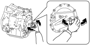
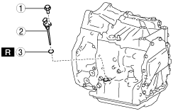
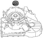
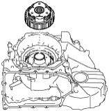
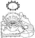
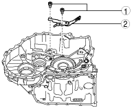
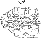
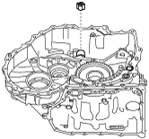
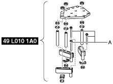
2. Remove the electric AT oil pump using the following procedure (only vehicles with i-stop).
bfw2za00000403
|
|
1
|
3 bolts
|
|
2
|
Electric AT oil pump
|
|
3
|
O-ring
|
azzjjw00001465
|
azzjjw00001466
|
azzjjw00001467
|
bfw2za00000404
|
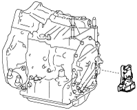
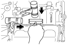
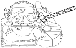
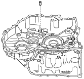
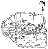
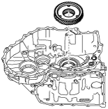
3. Remove the stud bolts.
azzjjw00000410
|
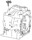
4. Remove the torque converter.
azzjjw00000411
|
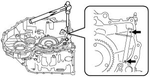
5. Remove the oil cooler in the order shown in the figure.
bfw2za00000030
|
|
1
|
Bolt
|
|
2
|
Oil cooler
|
|
3
|
O-ring
|
6. Remove the dipstick in the order shown in the figure.
bfw2za00000405
|
|
1
|
Bolt
|
|
2
|
Dipstick
|
|
3
|
O-ring
|
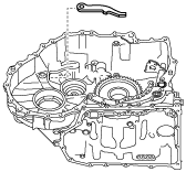
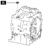
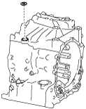
7. Remove the hose clamp.
bfw2za00000406
|
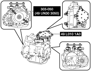
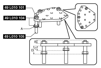
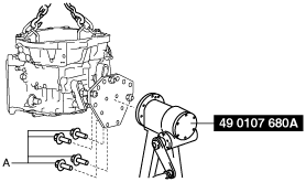
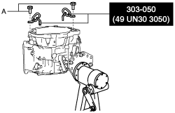
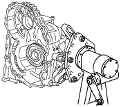
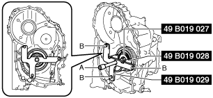
8. Install the transaxle to the SST (engine stand) using the following procedure:
bfw2za00000407
|
bfw2za00000408
|
bfw2za00000409
|
bfw2za00000410
|
bfw2za00000411
|
bfw2za00000412
|
bfw2za00000413
|
9. Remove the service hole cover. (With service hole cover)
10. Remove the oil pan and magnet using the following procedure:
azzjjw00001425
|
|
1
|
16 bolts
|
|
2
|
Oil pan
|
|
3
|
Magnet
|
azzjjw00000423
|
azzjjw00000424
|
azzjjw00000425
|
azzjjw00000426
|
11. Remove the oil strainer in the order shown in the figure.
bfw2za00000414
|
|
1
|
Bolt
|
|
2
|
Oil strainer
|
|
3
|
O-rings
|
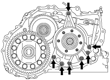
12. Remove the control valve body using the following procedure:
bfw2za00000415
|
|
1
|
11 bolts
|
|
2
|
Control valve body
|
|
3
|
Dowel pin
|
|
4
|
Gasket
|
azzjjw00000429
|
azzjjw00000430
|
azzjjw00000431
|
azzjjw00000432
|
bfw2za00000416
|
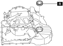
13. Remove the oil seal.
azzjjw00000434
|
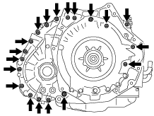
14. Remove the converter housing using the following procedure:
bfw2za00000417
|
|
1
|
25 bolts
|
|
2
|
Converter housing
|
|
3
|
O-ring (oil pump)
|
|
4
|
O-ring (oil cooler oil passage)
|
bfw2za00000032
|
bfw2za00000033
|
bfw2za00000418
|
bfw2za00000419
|
bfw2za00000420
|
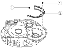
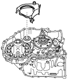
15. Remove the accessories from the converter housing using the following procedure:
bfw2za00000034
|
|
1
|
Bolt
|
|
2
|
Baffle plate
|
bfw2za00000421
|
bfw2za00000422
|
|
1
|
Bearing race
|
|
2
|
Shim
|
bfw2za00000423
|
bfw2za00000424
|
bfw2za00000425
|
bfw2za00000426
|
|
1
|
Bearing race
|
|
2
|
Shim
|
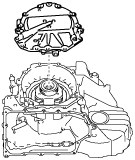
16. Remove the baffle plate.
azzjjw00000447
|
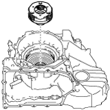
17. Remove the oil pump using the following procedure:
azzjjw00000448
|
|
1
|
7 bolts
|
|
2
|
Oil pump
|
azzjjw00000449
|
azzjjw00000450
|
18. Remove the thrust needle bearing.
azzjjw00000451
|
19. Remove the high clutch component and low clutch component
azzjjw00000452
|
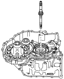
20. Remove the turbine shaft.
azzjjw00000453
|
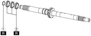
21. Remove the D-ring and seal rings from the turbine shaft using the procedure in the figure:
bfw2za00000427
|
|
1
|
D-ring
|
|
2
|
Seal ring
|
22. Remove the thrust needle bearing.
azzjjw00000455
|
23. Remove the high clutch hub.
azzjjw00000456
|
24. Remove the thrust needle bearing.
azzjjw00000457
|
25. Remove the low clutch hub.
azzjjw00000458
|
26. Remove the thrust needle bearing.
azzjjw00000459
|
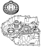
27. Remove the ring gear and differential.
azzjjw00000460
|
28. Remove the oil pipe.
azzjjw00000461
|
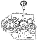
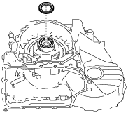
29. Remove the secondary gear and output gear.
azzjjw00000462
|
30. Remove the baffle plate using the procedure shown in the figure.
bfw2za00000428
|
|
1
|
Bolt
|
|
2
|
Baffle plate
|
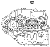
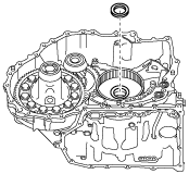
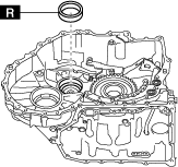
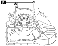
31. Remove the oil seal.
bfw2za00000429
|
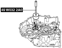
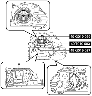
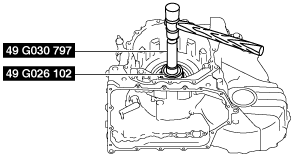
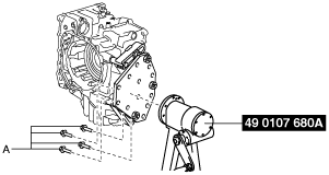
32. Remove the taper roller bearing using the following procedure:
bfw3ja00000343
|
bfw3ja00000344
|
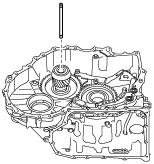
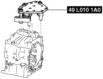
33. Remove the bearing race using the SST.
azzjjw00000468
|
bfw2za00000430
|
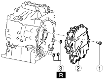
34. Remove end cover component using the following procedure:
bfw2za00000431
|
|
1
|
12 bolts
|
|
2
|
End cover component
|
|
3
|
O-ring
|
azzjjw00000471
|
azzjjw00000472
|
azzjjw00000473
|
azzjjw00000474
|
bfw2za00000432
|
35. Remove the shim.
azzjjw00000476
|
36. Remove the thrust needle bearing.
azzjjw00000477
|
37. Remove the reduction sun gear.
azzjjw00000478
|
38. Remove the thrust needle bearing.
azzjjw00000479
|
39. Remove the rear planetary gear.
azzjjw00000480
|
40. Remove the rear sun gear.
azzjjw00000481
|
41. Remove the front sun gear.
azzjjw00000482
|
42. Inspect the transaxle case, primary gear, and the angular contact ball bearing using the following procedure:
azzjjw00000483
|
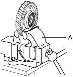
43. Remove the locknut using the following procedure:
azzjjw00000484
|
bfw2za00000433
|
bfw2za00000434
|
azzjjw00000487
|
bfw2za00000433
|
bfw2za00000435
|
44. Remove the front planetary gear.
azzjjw00000489
|
45. Perform a simple inspection of the low and reverse brake using the following procedure:
bfw2za00000436
|
46. Remove the snap ring using the following procedure:
bfw2za00000437
|
bfw2za00000438
|
bfw2za00000439
|
azzjjw00000494
|
bfw2za00000440
|
bfw2za00000437
|
47. Remove the one-way clutch.
azzjjw00000496
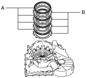
|
48. Remove the drive plates and driven plates.
azzjjw00000497
|
49. Remove the springs and retainer component.
azzjjw00000498
|
50. Remove the low and reverse brake piston using the following procedure:
bfw2za00000441
|
azzjjw00000500
|
51. Remove the connector, gaskets, oil pipe, and the O-rings in the order shown in the figure.
bfw2za00000442
|
|
1
|
Connector
|
|
2
|
Gasket
|
|
3
|
Oil pipe
|
|
4
|
O-ring
|
52. Remove the detent bracket component in the order shown in the figure.
azzjjw00000502
|
|
1
|
Bolt
|
|
2
|
Detent bracket component
|
53. Remove the pawl return springs.
azzjjw00000503
|
54. Remove the support actuator.
azzjjw00000504
|
55. Remove the parking pawl pin.
azzjjw00000505
|
56. Remove the parking rod component using the following procedure:
azzjjw00000506
|
azzjjw00000507
|
57. Remove the parking pawl shaft in the order shown in the figure.
bfw2za00000443
|
|
1
|
Plug
|
|
2
|
Gasket
|
|
3
|
Parking pawl shaft
|
58. Remove the parking pawl.
azzjjw00000509
|
59. Remove the roll pins shown in the figure using a pin punch.
azzjjw00000510
|
azzjjw00001498
|
60. Remove the parking shift lever component.
azzjjw00000512
|
61. Remove the parking assist lever component.
azzjjw00000513
|
62. Remove the manual plate component.
azzjjw00000514
|
63. Remove the oil seal.
bfw2za00000444
|
64. Remove the washer.
azzjjw00000516
|
65. Perform the following procedure only if there is a malfunction found in the Step 42 inspection.
azzjjw00000465
|
bfw2za00000445
|
azzjjw00000518
|
azzjjw00001205
|
bfw2za00000446
|
bfw2za00000447
|
bfw2za00000448
|
azzjjw00001208
|
azzjjw00000917
|
|
1
|
Plug
|
|
2
|
Gasket
|
66. Remove the SST from the transaxle case using the following procedure:
azzjjw00000521
|
bfw2za00000449
|
bfw2za00000450
|
bfw2za00000451
|
67. Disassemble the parts in the following order.
68. Clean away the remaining silicone sealant on the transaxle case, converter housing, end cover, oil pan, and the electric AT oil pump (only vehicles with i-stop).
69. Clean the disassembled parts. (See AUTOMATIC TRANSAXLE CLEANING.)
70. Perform the following inspection and replace a malfunctioning part with a new one.