|
1
|
VERIFY FREEZE FRAME DATA HAS BEEN RECORDED
• Has the FREEZE FRAME DATA been recorded?
|
Yes
|
Go to the next step.
|
|
No
|
Record the FREEZE FRAME DATA on the repair order, then go to the next step.
|
|
2
|
VERIFY RELATED REPAIR INFORMATION AVAILABILITY
• Verify related service repair information availability.
• Is any related repair information available?
|
Yes
|
Perform repair or diagnosis according to the available repair information.
• If the vehicle is not repaired, go to the next step.
|
|
No
|
Go to the next step.
|
|
3
|
VERIFY RELATED PENDING CODE AND/OR DTC
• Switch the ignition to ON (engine off).
• Perform the Pending Trouble Code Access Procedure and DTC Reading Procedure.
• Is the other PENDING CODE/DTC also present?
|
Yes
|
Go to the applicable DTC inspection.
|
|
No
|
Go to the next step.
|
|
4
|
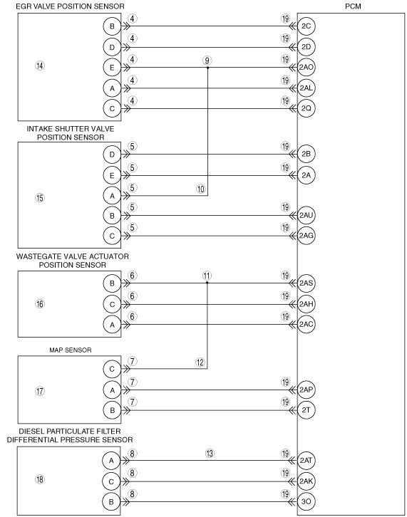
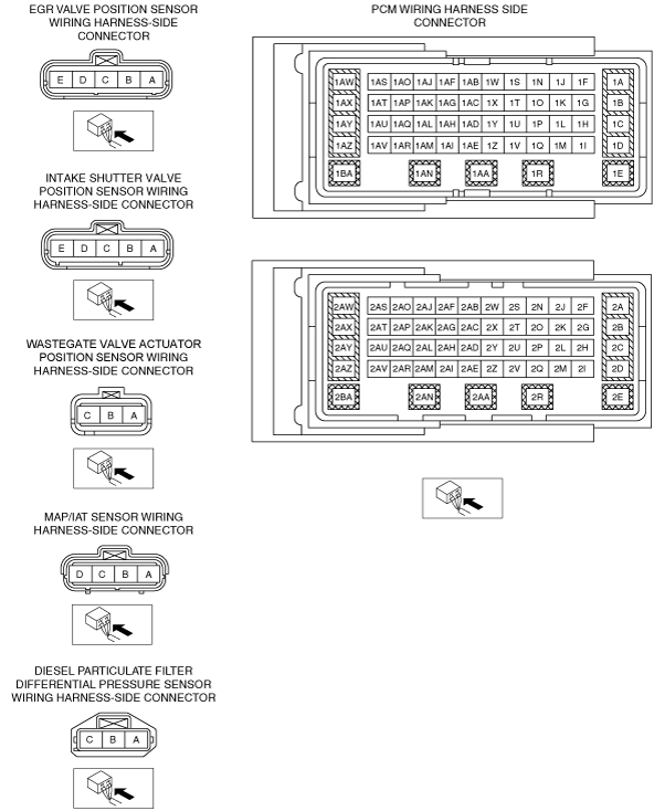
INSPECT EGR VALVE POSITION SENSOR CONNECTOR CONDITION
• Switch the ignition to off.
• Disconnect the EGR valve position sensor connector.
• Inspect for poor connection (such as damaged/pulled-out pins, corrosion)
• Is there any malfunction?
|
Yes
|
Repair or replace the connector and/or terminals, then go to Step 20.
|
|
No
|
Go to the next step.
|
|
5
|
INSPECT INTAKE SHUTTER VALVE POSITION SENSOR CONNECTOR CONDITION
• Disconnect the intake shutter valve position sensor connector.
• Inspect for poor connection (such as damaged/pulled-out pins, corrosion)
• Is there any malfunction?
|
Yes
|
Repair or replace the connector and/or terminals, then go to Step 20.
|
|
No
|
Go to the next step.
|
|
6
|
INSPECT WASTEGATE VALVE ACTUATOR POSITION SENSOR CONNECTOR CONDITION
• Disconnect the wastegate valve actuator position sensor connector.
• Inspect for poor connection (such as damaged/pulled-out pins, corrosion)
• Is there any malfunction?
|
Yes
|
Repair or replace the connector and/or terminals, then go to Step 20.
|
|
No
|
Go to the next step.
|
|
7
|
INSPECT MAP SENSOR CONNECTOR CONDITION
• Disconnect the MAP sensor connector.
• Inspect for poor connection (such as damaged/pulled-out pins, corrosion)
• Is there any malfunction?
|
Yes
|
Repair or replace the connector and/or terminals, then go to Step 20.
|
|
No
|
Go to the next step.
|
|
8
|
INSPECT DIESEL PARTICULATE FILTER DIFFERENTIAL PRESSURE SENSOR CONNECTOR CONDITION
• Disconnect the diesel particulate filter differential pressure sensor connector.
• Inspect for poor connection (such as damaged/pulled-out pins, corrosion)
• Is there any malfunction?
|
Yes
|
Repair or replace the connector and/or terminals, then go to Step 20.
|
|
No
|
Go to the next step.
|
|
9
|
INSPECT EGR VALVE POSITION SENSOR POWER CIRCUIT FOR SHORT TO GROUND
• Disconnect the EGR valve position sensor connector.
• Inspect for continuity between EGR valve position sensor terminal E (wiring harness-side) and body ground.
• Is there continuity?
|
Yes
|
Repair or replace the wiring harness for a possible short to ground, then go to Step 20.
|
|
No
|
Go to the next step.
|
|
10
|
INSPECT INTAKE SHUTTER VALVE POSITION SENSOR POWER CIRCUIT FOR SHORT TO GROUND
• Disconnect the intake shutter valve position sensor connector.
• Inspect for continuity between intake shutter valve position sensor terminal A (wiring harness-side) and body ground.
• Is there continuity?
|
Yes
|
Repair or replace the wiring harness for a possible short to ground, then go to Step 20.
|
|
No
|
Go to the next step.
|
|
11
|
INSPECT WASTEGATE VALVE ACTUATOR POSITION SENSOR POWER CIRCUIT FOR SHORT TO GROUND
• Disconnect the wastegate valve actuator position sensor connector.
• Inspect for continuity between wastegate valve actuator position sensor terminal B (wiring harness-side) and body ground.
• Is there continuity?
|
Yes
|
Repair or replace the wiring harness for a possible short to ground, then go to Step 20.
|
|
No
|
Go to the next step.
|
|
12
|
INSPECT MAP SENSOR POWER CIRCUIT FOR SHORT TO GROUND
• Disconnect the MAP sensor connector.
• Inspect for continuity between MAP sensor terminal C (wiring harness-side) and body ground.
• Is there continuity?
|
Yes
|
Repair or replace the wiring harness for a possible short to ground, then go to Step 20.
|
|
No
|
Go to the next step.
|
|
13
|
INSPECT DIESEL PARTICULATE FILTER DIFFERENTIAL PRESSURE SENSOR POWER CIRCUIT FOR SHORT TO GROUND
• Disconnect the diesel particulate filter differential pressure sensor connector.
• Inspect for continuity between diesel particulate filter differential pressure sensor terminal A (wiring harness-side) and body ground.
• Is there continuity?
|
Yes
|
Repair or replace the wiring harness for a possible short to ground, then go to Step 20.
|
|
No
|
Go to the next step.
|
|
14
|
INSPECT EGR VALVE POSITION SENSOR
• Inspect the EGR valve position sensor.
• Is there any malfunction?
|
Yes
|
Replace the EGR valve, then go to Step 20.
|
|
No
|
Go to the next step.
|
|
15
|
INSPECT INTAKE SHUTTER VALVE POSITION SENSOR
• Inspect the intake shutter valve position sensor.
• Is there any malfunction?
|
Yes
|
Replace the intake shutter valve, then go to Step 20.
|
|
No
|
Go to the next step.
|
|
16
|
INSPECT WASTEGATE VALVE ACTUATOR POSITION SENSOR
• Inspect the wastegate valve actuator position sensor.
• Is there any malfunction?
|
Yes
|
Replace the wastegate valve actuator position sensor, then go to Step 20.
|
|
No
|
Go to the next step.
|
|
17
|
INSPECT MAP SENSOR
• Inspect the MAP sensor.
• Is there any malfunction?
|
Yes
|
Replace the MAP sensor, then go to Step 20.
|
|
No
|
Go to the next step.
|
|
18
|
INSPECT DIESEL PARTICULATE FILTER DIFFERENTIAL PRESSURE SENSOR
• Inspect the diesel particulate filter differential pressure sensor.
• Is there any malfunction?
|
Yes
|
Replace the diesel particulate filter differential pressure sensor, then go to Step 20.
|
|
No
|
Go to the next step.
|
|
19
|
INSPECT PCM CONNECTOR CONDITION
• Disconnect the PCM connector.
• Inspect for poor connection (such as damaged/pulled-out pins, corrosion)
• Is there any malfunction?
|
Yes
|
Repair or replace the connector and/or terminals, then go to Step 15.
|
|
No
|
Go to the next step.
|
|
20
|
VERIFY THAT DTC P0642:00 TROUBLESHOOTING IS COMPLETED
• Make sure to reconnect all disconnected connectors.
• Clear the DTC from the PCM memory using the M-MDS.
• Run the vehicle under the FREEZE FRAME DATA stored condition.
• Is the same DTC present?
|
Yes
|
Repeat the inspection from Step 1.
• If the malfunction recurs, replace the PCM.
Go to the next step.
|
|
No
|
Go to the next step.
|
|
21
|
VERIFY AFTER REPAIR PROCEDURE
• Perform the after repair procedure.
• Are any DTCs present?
|
Yes
|
Go to the applicable DTC inspection.
|
|
No
|
DTC troubleshooting completed.
|