3
WILL NOT CRANK
DESCRIPTION
• Starter does not work.
POSSIBLE CAUSE
Vehicles without advanced keyless entry and push button start system:
• Coil antenna connector or terminals malfunction
• Instrument cluster and related wiring harness malfunction
• Immobilizer system malfunction
• PCM ground circuit malfunction
• Coil antenna circuit and related connectors malfunction
• Charging system malfunction
• Open circuit in wiring harness between PCM terminal 1B and starter relay
• Open or short circuit in wiring harness between starter relay and PCM
• Open or short circuit in wiring harness between starter relay and ignition switch
• Ignition switch and related wiring harness malfunction
• Open or short circuit in wiring harness between starter relay and battery positive terminal
• Open or short circuit in wiring harness between starter relay and starter
• Starter malfunction
• Seized/hydro locked engine, flywheel
• PCM continuous memory DTC is stored
• Starter circuit in ignition switch
• Open circuit in wiring harness between ignition switch and starter
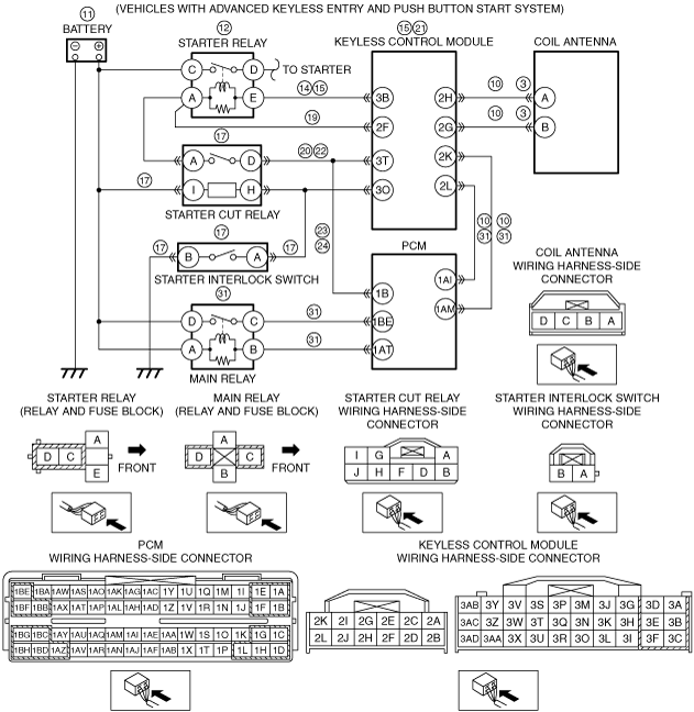
Vehicles with advanced keyless entry and push button start system:
• Advanced keyless entry and push button start system malfunction
• Coil antenna connector or terminals malfunction
• Instrument cluster and related wiring harness malfunction
• Immobilizer system malfunction
• PCM ground circuit malfunction
• Coil antenna circuit and related connectors malfunction
• Charging system malfunction
• Starter relay malfunction
• Open circuit in wiring harness between keyless control module terminal 3B and starter relay terminal E
• Short to ground in wiring harness between keyless control module terminal 3B and starter relay terminal E
• Keyless control module malfunction
• Open or short circuit in wiring harness between battery positive terminal and starter cut relay
• Starter cut relay malfunction
• Open or short circuit in wiring harness between starter cut relay and starter interlock switch
• Open or short circuit in wiring harness between starter interlock switch and body ground
• Starter interlock switch malfunction
• Open or short circuit in wiring harness between starter relay terminal A and keyless control module terminal 2F
• Open circuit in wiring harness between keyless control module terminal 3T and starter cut relay terminal D
• Starter and related wiring harness malfunction
• Open circuit in wiring harness between starter cut relay terminal D and PCM terminal 1B
• Open circuit in wiring harness between PCM terminal 1B and starter relay
• Starter interlock switch and related wiring harness malfunction
• Open or short circuit in wiring harness between starter relay and PCM
• Open or short circuit in wiring harness between starter relay and ignition switch
• Ignition switch and related wiring harness malfunction
• Open or short circuit in wiring harness between starter relay and battery positive terminal
• Open or short circuit in wiring harness between starter relay and starter
• Starter malfunction
• Seized/hydro locked engine, flywheel
• PCM continuous memory DTC is stored
• Starter circuit in ignition switch
• Open circuit in wiring harness between ignition switch and starter