|
am3zzw00010405
CYLINDER HEAD GASKET REPLACEMENT [MZR 2.3 DISI Turbo]
id0110d9800700
1. Remove the intake manifold. (See INTAKE-AIR SYSTEM REMOVAL/INSTALLATION [MZR 2.3 DISI Turbo].)
2. Remove the exhaust manifold. (See EXHAUST SYSTEM REMOVAL/INSTALLATION [MZR 2.3 DISI Turbo].)
3. Remove the generator. (See GENERATOR REMOVAL/INSTALLATION [MZR 2.3 DISI Turbo].)
4. Disconnect the heater hose. (See A/C UNIT REMOVAL/INSTALLATION.)
5. Disconnect the upper radiator hose. (See RADIATOR REMOVAL/INSTALLATION [MZR 2.3 DISI Turbo].)
6. Remove the timing chain. (See TIMING CHAIN REMOVAL/INSTALLATION [MZR 2.3 DISI Turbo].)
7. Disconnect the connectors and the wiring harnesses related to the cylinder head gasket removal/installation.
8. Remove in the order indicated in the table.
9. Install in the reverse order of removal.
10. Bleed the air from the cooling system. (See ENGINE COOLANT REPLACEMENT [MZR 2.3 DISI Turbo].)
11. Inspect the compression. (See COMPRESSION INSPECTION [MZR 2.3 DISI Turbo].)
am3zzw00010405
|
|
1
|
OCV
|
|
2
|
Camshaft
(See Camshaft Removal Note.)
(See Camshaft Installation Note.)
|
|
3
|
Cylinder head
(See Cylinder Head Removal Note.)
|
|
4
|
Cylinder head gasket
|
Camshaft Removal Note
1. Loosen the camshaft cap bolts in 2—3 steps in the order shown in the figure.
am3zzw00010243
|
Cylinder Head Removal Note
1. Loosen the cylinder head bolts in 2—3 steps in the order shown in the figure.
am3zzw00010244
|
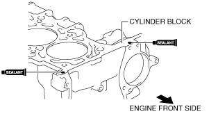
Cylinder Head Gasket Installation Note
1. Apply silicone sealant to the areas shown in the figure.
am3zzw00016620
|
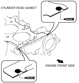
2. Install a new cylinder head gasket to the cylinder block.
3. Apply silicone sealant to the areas shown in the figure.
am3zzw00016621
|
4. Install the cylinder head referring to the Cylinder Head Installation Note.
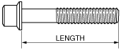
Cylinder Head Installation Note
1. Measure the length of each cylinder head bolt.
am3zzw00010245
|
2. Tighten the cylinder head bolts in 5 steps in the order shown in the figure using the SST (49 D032 316).
am3zzw00010246
|
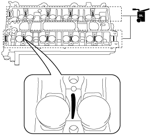
Camshaft Installation Note
1. Apply the gear oil (SAE No. 90 or equivalent) to each journal of the cylinder head as shown in the figure.
am3zzw00015510
|
2. With No.1 cylinder cam aligned at TDC of the compression stroke, install the camshafts.
3. Apply the gear oil (SAE No. 90 or equivalent) to each journal of the camshaft as shown in the figure. However, do not apply it to the end journal of the intake camshaft.
am3zzw00015511
|
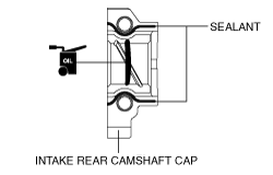
4. Carefully apply sealant agent (Loctite 518 or 962T) to the area indicated in the figure so that it does not leak into the sliding part, then apply the gear oil (SAE No. 90 or equivalent) to the journal.
beltze00000119
|
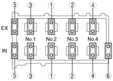
5. Temporarily tighten the camshaft cap bolts evenly in 2—3 steps.
6. Tighten the camshaft cap bolts in two steps in the order shown in the figure.
am3zzw00010248
|