 |
am3zzw00013068
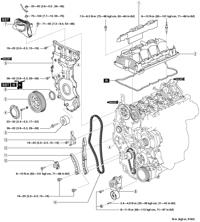
TIMING CHAIN REMOVAL/INSTALLATION [MZR-CD 2.2]
id0110f2801000
|
STEP |
ACTION |
PAGE/CONDITION |
|---|---|---|
|
1
|
Replace the timing chain.
|
—
|
|
2
|
Start the engine.
|
—
|
|
3
|
Perform the injection amount correction procedure.
|
Engine coolant temperature: 65—95 °C {149—203 °F}
Intake air temperature: 15—65 °C {59—149 °F}
Fuel temperature: 30—60 °C {86—140 °F}
|
|
4
|
Perform the timing chain correction procedure.
|
Engine coolant temperature: 65—95 °C {149—203 °F}
Intake air temperature: 15—65 °C {59—149 °F}
Fuel temperature: 30—60 °C {86—140 °F}
|
|
5
|
Perform after repair procedure.
|
|
|
6
|
Switch the ignition to off.
|
—
|
1. Complete the “BEFORE SERVICE PRECAUTION”. (See BEFORE SERVICE PRECAUTION [MZR-CD 2.2].)
2. Drain the engine oil. (See ENGINE OIL REPLACEMENT [MZR-CD 2.2].)
3. Disconnect the negative battery cable. (See BATTERY REMOVAL/INSTALLATION [MZR-CD 2.2].)
4. Remove the engine cover. (See ENGINE COVER REMOVAL/INSTALLATION [MZR-CD 2.2].)
5. Disconnect the ventilation hose.
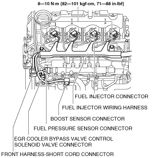
6. Disconnect the following parts and set the fuel injector wiring harness out of the way.
am3zzw00013068
|
7. Remove the fuel injectors. (See FUEL INJECTOR REMOVAL/INSTALLATION [MZR-CD 2.2].)
8. Remove the camshaft position sensor. (See CAMSHAFT POSITION (CMP) SENSOR REMOVAL/INSTALLATION [MZR-CD 2.2].)
9. Remove the front wheel and tire. (RH) (See GENERAL PROCEDURES (SUSPENSION).)
10. Remove the aerodynamic under cover No.2 and splash shield as a single unit. (See AERODYNAMIC UNDER COVER NO.2 REMOVAL/INSTALLATION.) (See SPLASH SHIELD REMOVAL/INSTALLATION.)
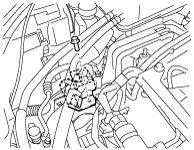
11. Remove the nut shown in the figure and set the power steering pipe component out of the way.
am3zzw00013069
|
12. Remove the drive belt. (See DRIVE BELT REMOVAL/INSTALLATION [MZR-CD 2.2].)
13. Remove the crankshaft position sensor. (See CRANKSHAFT POSITION (CKP) SENSOR REMOVAL/INSTALLATION [MZR-CD 2.2].)
14. Remove the fuel filter component with the hose still connected and set it out of the way. (L.H.D.) (See FUEL FILTER REMOVAL/INSTALLATION [MZR-CD 2.2].)
15. Remove the coolant reserve tank with the hose still connected and set it out of the way. (See COOLANT RESERVE TANK REMOVAL/INSTALLATION [MZR-CD 2.2].)
16. Remove in the order shown in the table.
17. Install in the reverse order of removal.
18. Complete the “AFTER SERVICE PRECAUTION”. (See AFTER SERVICE PRECAUTION [MZR-CD 2.2].)
19. Refill the engine oil. (See ENGINE OIL REPLACEMENT [MZR-CD 2.2].)
20. Start the engine, and inspect and adjust the following:
am3zzw00010877
|
|
1
|
Insulator
|
|
2
|
Cylinder head cover
|
|
3
|
Idler
|
|
4
|
Crankshaft pulley cover
|
|
5
|
Crankshaft pulley
|
|
6
|
Front oil seal
|
|
7
|
No.3 engine mount
|
|
8
|
Drive belt auto tensioner
|
|
9
|
Engine front cover
|
|
10
|
Timing chain tensioner
|
|
11
|
Timing chain tensioner arm
|
|
12
|
Timing chain guide No.1
|
|
13
|
Timing chain guide No.2
|
|
14
|
Timing chain
|
Cylinder Head Cover Removal Note
1. Remove the bolts in the order shown in the figure.
am3zzw00013070
|
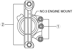
No.3 Engine Mount Removal Note
1. Detach the hose clip shown in the figure.
am3zzw00006855
|
2. Remove the bracket bolt shown in the figure and set the bracket aside to prevent interference with the SST.
am3zzw00006856
|
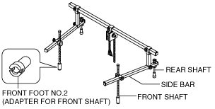
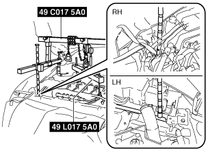
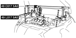
3. Install the SST using the following procedure.
am3zzw00013071
|
am3zzw00006858
|
am3zzw00006859
|
4. Support the engine using the SST.
am3zzw00006860
|
5. Remove the No.3 engine mount.
Drive Belt Auto Tensioner Removal Note
1. Remove the drive belt auto tensioner installation bolt and nuts.
am3zzw00013072
|
2. Remove the drive belt auto tensioner stud bolts.
am3zzw00013073
|
3. Remove the drive belt auto tensioner.
Timing Chain Tensioner Removal Note
1. Rotate the crankshaft clockwise and align the knock pin to the position shown in the figure. In this position, the No.1 cylinder is at the TDC of the compression stroke.
am3zzw00013074
|
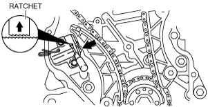
2. Push up the ratchet using a screwdriver and slowly compress the piston.
am3zzw00013075
|
3. Hold the piston using a wire or paper clip.
4. Remove the timing chain tensioner.
Timing Chain Installation Note
am3zzw00009683
|
am3zzw00013076
|
1. Set the timing chain with the timing chain alignment mark aligned with the exhaust camshaft sprocket alignment mark as well as the crankshaft sprocket alignment mark.
am3zzw00010878
|
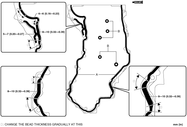
Engine Front Cover Installation Note
1. Apply sealant as shown in the figure.
am3zzw00013077
|
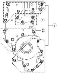
2. Tighten the bolts in the order shown in the figure.
am3zzw00013078
|
Drive Belt Auto Tensioner Installation Note
1. Align the drive belt auto tensioner with the installation position and install the stud bolts.
am3zzw00013073
|
2. Temporarily tighten the drive belt auto tensioner installation bolt and nuts.
am3zzw00013072
|
3. Tighten the drive belt auto tensioner installation bolt and nuts.
am3zzw00013079
|
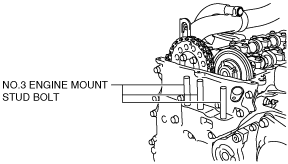
No.3 Engine Mount Installation Note
1. Tighten the No.3 engine mount stud bolts.
am3zzw00013080
|
2. Temporarily tighten the No.3 engine mount installation bolts and nuts.
3. Tighten the No.3 engine mount installation bolts and nuts in the order shown in the figure.
am3zzw00007783
|
Cylinder Head Cover Installation Note
1. Apply sealant as shown in the figure.
am3zzw00013081
|
2. After temporarily tightening bolt A, tighten it in the order shown in the figure.
am3zzw00013082
|
3. Tighten the bolts in the order shown in the figure.
am3zzw00013083
|