 |
am3zzw00007239
DSC HU/CM REMOVAL/INSTALLATION
id041500801000
1. Remove the battery and battery tray. (except MZR 2.0 DISI i-stop) (See BATTERY REMOVAL/INSTALLATION [MZR 1.5, MZR 1.6].) (See BATTERY REMOVAL/INSTALLATION [MZR 2.0, MZR 2.5].) (See BATTERY REMOVAL/INSTALLATION [SKYACTIV-G 2.0].) (See BATTERY REMOVAL/INSTALLATION [MZR 2.3 DISI Turbo].) (See BATTERY REMOVAL/INSTALLATION [MZ-CD 1.6].) (See BATTERY REMOVAL/INSTALLATION [MZR-CD 2.2].)
2. Remove the main battery, sub battery and battery tray. (MZR 2.0 DISI i-stop) (See BATTERY REMOVAL/INSTALLATION [MZR 2.0 DISI i-stop].)
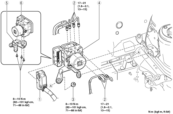
3. Remove in the order indicated in the table.
4. Install in the reverse order of removal.
5. Switch the ignition to ON or start the engine, and maintain this condition for approx. 30 s to allow the DSC HU/CM automatic configuration to be performed.
6. Perform the DSC sensor initialization procedures. (See DSC SENSOR INITIALIZATION PROCEDURE.)
7. Clear the DTCs from the memory. (See ON-BOARD DIAGNOSIS [DYNAMIC STABILITY CONTROL (DSC)].)
am3zzw00007239
|
|
1
|
Connector
|
|
2
|
Brake pipe
(See Brake Pipe Removal Note.)
(See Brake Pipe Installation Note.)
|
|
3
|
Bolt
|
|
4
|
DSC HU/CM, bracket
|
|
5
|
Bracket
|
|
6
|
DSC HU/CM
|
Brake Pipe Removal Note
1. Place an alignment mark on the brake pipe and DSC HU/CM.
am3uuw00002728
|
2. Apply protective tape to the connector to prevent brake fluid from entering.
3. Remove the brake pipe.
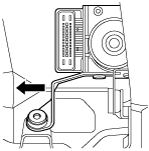
DSC HU/CM, Bracket Removal Note
1. As shown in the figure, move the bracket in the direction of the arrow and remove the DSC HU/CM and bracket from the body.
am3uuw00002729
|
Brake Pipe Installation Note
1. Align the marks made before removal and install the brake pipe into the DSC HU/CM referring to the figure.
am3uuw00002730
|