|
1
|
VERIFY FREEZE FRAME DATA HAS BEEN RECORDED
• Has the FREEZE FRAME DATA been recorded on the repair order?
|
Yes
|
Go to the next step.
|
|
No
|
Record the FREEZE FRAME DATA on the repair order, then go to the next step.
|
|
2
|
VERIFY RELATED REPAIR INFORMATION AVAILABILITY
• Verify related Service Information availability.
• Is any related repair information available?
|
Yes
|
Perform repair or diagnosis according to the available repair information.
• If the vehicle is not repaired, go to the next step.
|
|
No
|
Go to the next step.
|
|
3
|
INSPECT COUPLER COMPONENT CONNECTOR FOR POOR CONNECTION
• Switch the ignition off.
• Disconnect the coupler component connector.
• Inspect for poor connection (such as damaged/pulled-out pins, corrosion)
• Is there any malfunction?
|
Yes
|
Repair or replace the terminal, then go to Step 8.
|
|
No
|
Go to the next step.
|
|
4
|
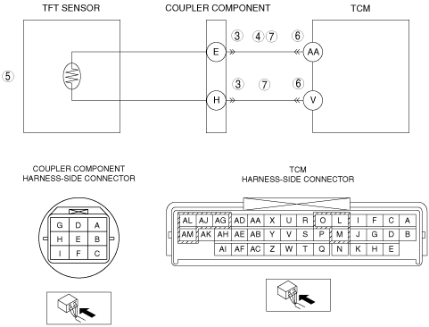
INSPECT TFT SENSOR SIGNAL CIRCUIT FOR SHORT TO POWER SUPPLY
• Switch the ignition to ON (Engine off).
• Measure the voltage between coupler component terminal E (wiring harness-side) and body GND.
• Is the voltage B+?
|
Yes
|
Repair or replace the wiring harness for a possible short to power supply, then go to Step 8.
|
|
No
|
Go to the next step.
|
|
5
|
INSPECT TFT SENSOR
• Inspect the TFT sensor.
• Is there any malfunction?
|
Yes
|
Replace the coupler component, then go to Step 8.
|
|
No
|
Go to the next step.
|
|
6
|
INSPECT TCM CONNECTOR FOR POOR CONNECTION
• Switch the ignition off.
• Disconnect the TCM connector.
• Inspect for poor connection (such as damaged/pulled-out pins, corrosion)
• Is there any malfunction?
|
Yes
|
Repair or replace the terminal, then go to Step 8.
|
|
No
|
Go to the next step.
|
|
7
|
INSPECT TFT SENSOR CIRCUIT FOR OPEN CIRCUIT
• Switch the ignition off.
• Inspect for continuity between the following circuits:
-
― Coupler component terminal E (wiring harness-side) and TCM terminal AA (wiring harness-side)
― Coupler component terminal H (wiring harness-side) and TCM terminal V (wiring harness-side)
• Is there continuity?
|
Yes
|
Go to the next step.
|
|
No
|
Repair or replace the wiring harness for a possible open circuit, then go to the next step.
|
|
8
|
VERIFY DTC TROUBLESHOOTING COMPLETED
• Make sure to reconnect all the disconnected connectors.
• Clear the DTC using the M-MDS.
• Perform the following procedure to ensure that the DTC has been resolved:
-
1. Start the engine.
2. Idle the engine for 180 s or more.
• Is the PENDING CODE same as the DTC present?
|
Yes
|
Replace the TCM, then go to the next step.
|
|
No
|
Go to the next step.
|
|
9
|
VERIFY NO DTCs ARE PRESENT
• Perform the “Reading DTCs Procedure”.
• Are any DTCs present?
|
Yes
|
Go to the applicable DTC inspection.
|
|
No
|
DTC troubleshooting completed.
|