TRANSAXLE FLUID TEMPERATURE (TFT) SENSOR REMOVAL/INSTALLATION [FS5A-EL]
id051721292200
-
Warning
-
• A hot transaxle and ATF can cause severe burns. Turn off the engine and wait until they are cool.
1. Remove the primary control valve body.
- (1) Remove the battery cover. (See BATTERY REMOVAL/INSTALLATION [MZR 2.0, MZR 2.5].)
- (2) Disconnect the negative battery cable.
- (3) Remove the aerodynamic under cover No.2. (See AERODYNAMIC UNDER COVER NO.2 REMOVAL/INSTALLATION.)
- (4) Clean the transaxle exterior throughout with a steam cleaner or cleaning solvents.
- (5) Drain the ATF. (See AUTOMATIC TRANSAXLE FLUID (ATF) REPLACEMENT [FS5A-EL].)
- (6) Remove the oil pan.
- (7) Remove the primary control valve body. (See CONTROL VALVE BODY REMOVAL/INSTALLATION [FS5A-EL].)
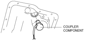
- (8) Disconnect the coupler component connector.
-
2. Remove the coupler component from transaxle case.
3. Remove the O-ring from the coupler component.
4. Install the primary control valve body.
- (1) Apply ATF to a new O-ring and install it on the coupler component.
- (2) Install the coupler component to transaxle case.
- (3) Connect the coupler component connector.
- (4) Install the primary control valve body. (See CONTROL VALVE BODY REMOVAL/INSTALLATION [FS5A-EL].)
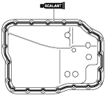
5. Apply a light coat of silicon sealant (TB1217E or equivalent) to the contact surfaces of the oil pan and transaxle case.
-
Caution
-
• If any old sealant gets into the transaxle during installation of the oil pan, trouble may occur in the transaxle case and oil pan, and clean with cleaning fluids.
6. Install the oil pan before the applied sealant starts to harden.
-
Caution
-
• The removed bolts with spring washer cannot be reused. If they are reused, it could loosen the bolts due to spring weakness.
-
Tightening torque
-
Flange bolt: 6.0—8.0 N·m {62—81 kgf·cm, 54—70 in·lbf}
Bolt with spring washer: 8—10 N·m {82—101 kgf·cm, 71—88 in·lbf}
7. Add ATF. (See AUTOMATIC TRANSAXLE FLUID (ATF) REPLACEMENT [FS5A-EL].)
8. Install the aerodynamic under cover No.2. (See AERODYNAMIC UNDER COVER NO.2 REMOVAL/INSTALLATION.)
9. Connect the negative battery cable.
10. Install the battery cover. (See BATTERY REMOVAL/INSTALLATION [MZR 2.0, MZR 2.5].)
11. Perform the “Mechanical System Test”. (See MECHANICAL SYSTEM TEST [FS5A-EL].)