am3zzw00009822
|
MANUAL TRANSAXLE REMOVAL/INSTALLATION [B76M-R]
id0515m7160000
1. Disconnect the negative battery cable.
2. Remove the aerodynamic under cover No.2 and the splash shield as a single unit. (See AERODYNAMIC UNDER COVER NO.2 REMOVAL/INSTALLATION.) (See SPLASH SHIELD REMOVAL/INSTALLATION.)
3. Drain the manual transaxle oil. (See MANUAL TRANSAXLE OIL REPLACEMENT [B76M-R].)
4. Disconnect and/or remove the following parts in the engine compartment.
5. Disconnect and/or remove the following parts related to the suspension and axle.
6. Disconnect and/or remove the following parts from the underside of the vehicle.
am3zzw00009822
|
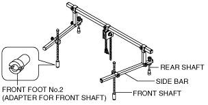
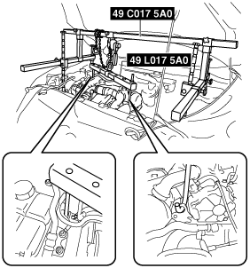
7. Install the SST using the following procedure.
am6xuw00001516
|
am3zzw00009828
|
am3zzw00009829
|
am3zzw00005439
|
am3zzw00009830
|
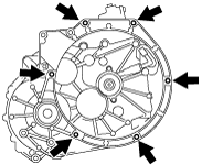
8. Remove in the order indicated in the table.
9. Install in the reverse order of removal.
10. Add the specified amount of specified transaxle oil. (See MANUAL TRANSAXLE OIL REPLACEMENT [B76M-R].)
11. Bleed the air from the clutch system. (See CLUTCH FLUID REPLACEMENT/AIR BLEEDING [B76M-R].)
12. If the manual transaxle is overhauled, perform the “INSPECTION AFTER MANUAL TRANSAXLE OVERHAUL”. (See INSPECTION AFTER MANUAL TRANSAXLE OVERHAUL [B76M-R].)
am3zzw00013323
|
|
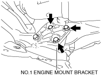
1
|
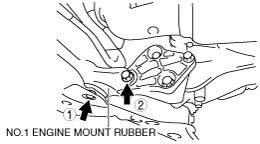
No.1 engine mount bracket
|
|
2
|
Transaxle mounting bolt (upper side)
|
|
3
|
Dynamic damper
|
|
4
|
Battery tray bracket
|
|
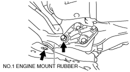
5
|
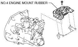
No.4 engine mount rubber
|
|
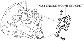
6
|
No.4 engine mount bracket
|
|
7
|
Transaxle mounting bolt (lower side)
|
|
8
|
Manual transaxle
|
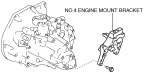
No.4 Engine Mount Bracket Removal Note
1. Remove the No.4 engine mount bracket installation bolt (upper).
am5ezw00006597
|
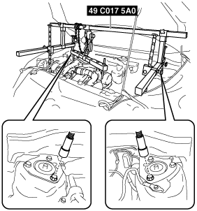
2. Tilt the engine and transaxle using the SST as shown in the figure.
am3zzw00009833
|
3. Remove the No.4 engine mount bracket.
am5ezw00006599
|
Transaxle Mounting Bolt (Lower Side) Removal Note
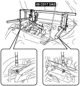
1. Adjust the SST and lean the engine toward the transaxle.
am3zzw00009834
|
2. Support the transaxle on a jack.
am3uuw00002584
|
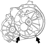
3. Remove the transaxle mounting bolts as shown in the figure.
am5ezw00006600
|
4. Remove the transaxle mounting bolts as shown in the figure.
am5ezw00006601
|
am2zzw00003886
|
am2zzw00003888
|
5. Remove the transaxle from the vehicle.
Manual Transaxle Installation Note
1. Set the transaxle on a jack and lift into place.
am3uuw00002584
|
2. Install the transaxle mounting bolts.
am5ezw00006611
|
3. Adjust the SST (49 C017 5A0) so that the engine is located at the specified position.
No.1 Engine Mount and No.4 Engine Mount Installation Note
1. Install the No.4 engine mount bracket to the transaxle case.
am5ezw00006602
|
2. Install the No.1 engine mount bracket to the transaxle case.
am5ezw00006612
|
3. Temporarily tighten the bolts as shown in the figure.
am5ezw00006613
|
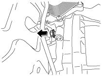
4. Place the No.4 engine mount rubber with the body stud bolts passing through the holes and tighten the bolt in the figure.
am5ezw00006604
|
5. Fully tighten the bolts in the order shown in the figure.
am5ezw00006622
|
6. Place the battery bracket on the No.4 Engine mount rubber with the body stud bolts passing through the holes and tighten bolts and nuts in the order shown in the figure.
am5ezw00006605
|
7. Remove the SST (49 C017 5A0).