 |
am3uuw00008416
DRIVE SHAFT REMOVAL/INSTALLATION
id031300801900
1. Remove the aerodynamic under cover No.2 and splash shield as a unit. (See AERODYNAMIC UNDER COVER NO.2 REMOVAL/INSTALLATION.) (See SPLASH SHIELD REMOVAL/INSTALLATION.)
2. Drain the transaxle oil or ATF. (See TRANSAXLE OIL REPLACEMENT [F35M-R].) (See MANUAL TRANSAXLE OIL REPLACEMENT [B76M-R].) (See TRANSAXLE OIL REPLACEMENT [G66M-R].) (See TRANSAXLE OIL REPLACEMENT [A26M-R].) (See CVT (CONTINUOUSLY VARIABLE TRANSAXLE) FLUID REPLACEMENT [DJVA-EL].) (See AUTOMATIC TRANSAXLE FLUID (ATF) REPLACEMENT [FN4A-EL].) (See AUTOMATIC TRANSAXLE FLUID (ATF) REPLACEMENT [FS5A-EL].) (See AUTOMATIC TRANSAXLE FLUID (ATF) REPLACEMENT [FW6A-EL].)
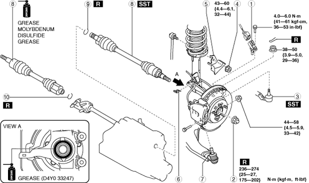
3. Remove in the order indicated in the table.
4. Install in the reverse order of removal.
am3uuw00008416
|
|
1
|
ABS wheel-speed sensor
|
|
2
|
Locknut
|
|
3
|
Tie-rod end ball joint
|
|
4
|
Stabilizer control link upper nut
|
|
5
|
Dynamic damper
|
|
6
|
Brake hose clip
|
|
7
|
Front lower arm ball joint
|
|
8
|
Drive shaft
(See Drive Shaft Removal Note.)
|
|
9
|
Drive shaft clip
|
|
10
|
Joint shaft clip
|
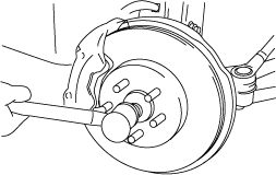
Drive Shaft Removal Note
1. Install a spare nut onto the drive shaft.
2. Tap the nut with a copper hammer and separate the drive shaft from the axle.
am3zzw00008759
|
3. Separate the drive shaft from the wheel hub.
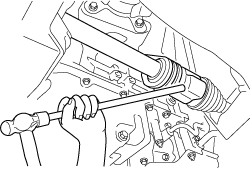
4. Separate the drive shaft (LH) from the transaxle using the SSTs.
am3uuw00004702
|
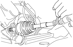
5. Disconnect the drive shaft (RH) from the joint shaft by tapping the transaxle side outer ring with a brass bar and hammer.
am3zzw00008760
|
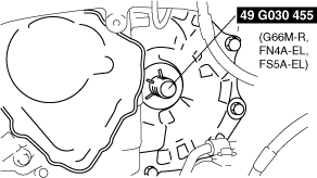
6. Install the SST to the transaxle after the drive shaft is removed.
am3zzw00013211
|
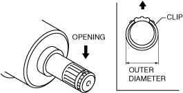
Drive Shaft Clip Installation Note
1. Install a new drive shaft clip to the clip groove at the end of the drive shaft with the clip opening facing upward and the clip width within the specification.
am3zzw00008761
|
2. After installation, measure the outer diameter.
Drive Shaft Installation Note
Left side
1. Insert the drive shaft into the wheel hub.
2. Apply transaxle oil to the oil seal lip.
3. Apply grease (D4Y0 33247) to the wheel bearing inner race and drive shaft contact surface (Area A in figure).
am3uuw00006176
|
4. Install the drive shaft to the transaxle.
am3zzw00008762
|
5. After installation, pull the transaxle side outer ring forward to confirm that the drive shaft is securely held by the clip.
Right side
1. Install a new clip onto the joint shaft. (See JOINT SHAFT REMOVAL/INSTALLATION [MZR 1.5, MZR 1.6, MZR 2.3 DISI Turbo, MZR 2.5].) (See JOINT SHAFT REMOVAL/INSTALLATION [MZR 2.0, MZR 2.0 DISI i-stop].) (See JOINT SHAFT REMOVAL/INSTALLATION [SKYACTIV-G 2.0].) (See JOINT SHAFT REMOVAL/INSTALLATION [MZ-CD 1.6, MZR-CD 2.2].)
2. Apply grease (D4Y0 33247) to the wheel bearing inner race and drive shaft contact surface (Area A in figure).
am3uuw00004355
|
3. Insert the drive shaft to the wheel hub.
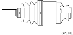
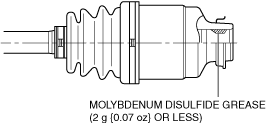
4. Inspect the drive shaft and spline shown in the figure for grease.
am3zzw00011433
|
am3uuw00008418
|
5. Insert the drive shaft to the joint shaft.
6. After installation, pull the transaxle side outer ring forward to confirm that the drive shaft is securely held by the clip.
Front Lower Arm Ball Joint Installation Note