 |
am3uuw00002426
CONTROL VALVE BODY REMOVAL/INSTALLATION [FS5A-EL]
id051721294600
Primary Control Valve Body On-Vehicle Removal
1. Remove the battery cover. (See BATTERY REMOVAL/INSTALLATION [MZR 2.0, MZR 2.5].)
2. Disconnect the negative battery cable.
3. Remove the aerodynamic under cover No.2. (See AERODYNAMIC UNDER COVER NO.2 REMOVAL/INSTALLATION.)
4. Clean the transaxle exterior throughout with a steam cleaner or cleaning solvents.
5. Drain the ATF. (See AUTOMATIC TRANSAXLE FLUID (ATF) REPLACEMENT [FS5A-EL].)
6. Remove the oil pan.
7. Remove the oil strainer.
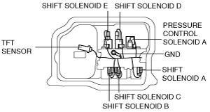
8. Disconnect each solenoid valve connector and GND.
am3uuw00002426
|
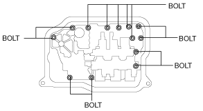
9. Remove the bolts as shown, then remove the primary control valve body.
am3uuw00002460
|
10. Remove the accumulators and accumulator springs.
am6xuw00001958
|
Primary Control Valve Body On-Vehicle Installation
am6xuw00001959
|
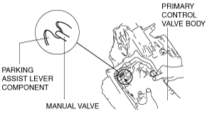
1. Install the accumulator springs, accumulators and primary control valve body.
am3uuw00002461
|
Accumulator spring specification
|
Spring |
Outer diameter (mm {in}) |
Free Length (mm {in}) |
No. of coils |
Wire diameter (mm {in}) |
|---|---|---|---|---|
|
Servo apply accumulator large spring
|
21.0 {0.827}
|
67.8 {2.669}
|
10.3
|
3.5 {0.138}
|
|
Servo apply accumulator small spring
|
13.0 {0.512}
|
67.8 {2.669}
|
17.1
|
2.2 {0.087}
|
|
Forward accumulator large spring
|
21.0 {0.827}
|
75.0 {2.953}
|
10.7
|
2.3 {0.091}
|
|
Forward accumulator small spring
|
15.6 {0.614}
|
49.0 {1.929}
|
7.7
|
2.4 {0.094}
|
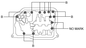
2. Tighten the bolts as shown to install the primary control valve body.
am3uuw00002462
|
Bolt length measured from below the head
|
Mark |
Length measured from below the head |
|---|---|
|
B
|
40mm {1.575 in}
|
|
No mark
|
70mm {2.756 in}
|
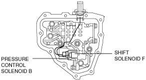
3. Match the harness colors, then connect each solenoid valves connector.
Connector color (harness-side)
|
Solenoid valve |
Connector color |
|---|---|
|
Pressure control solenoid A
|
Black
|
|
Shift solenoid A
|
White
|
|
Shift solenoid B
|
Blue
|
|
Shift solenoid C
|
Green
|
|
Shift solenoid D
|
White
|
|
Shift solenoid E
|
Black
|
4. Install the GND.
am3uuw00002426
|
5. Install the TFT sensor to the oil strainer.
6. Install the oil strainer.
7. Apply a light coat of silicon sealant (TB1217E or equivalent) to the contact surfaces of the oil pan and transaxle case.
am3uuw00002427
|
8. Install the oil pan before the applied sealant starts to harden.
9. Add ATF. (See AUTOMATIC TRANSAXLE FLUID (ATF) REPLACEMENT [FS5A-EL].)
10. Install the aerodynamic under cover No.2. (See AERODYNAMIC UNDER COVER NO.2 REMOVAL/INSTALLATION.)
11. Connect the negative battery cable.
12. Install the battery cover. (See BATTERY REMOVAL/INSTALLATION [MZR 2.0, MZR 2.5].)
13. Perform the “Mechanical System Test”. (See MECHANICAL SYSTEM TEST [FS5A-EL].)
14. Perform the “Road Test”. (See ROAD TEST [FS5A-EL].)
Secondary Control Valve Body On-Vehicle Removal
1. Remove the battery cover. (See BATTERY REMOVAL/INSTALLATION [MZR 2.0, MZR 2.5].)
2. Disconnect the negative battery cable.
3. Remove the battery. (See BATTERY REMOVAL/INSTALLATION [MZR 2.0, MZR 2.5].)
4. Remove the battery box. (See BATTERY REMOVAL/INSTALLATION [MZR 2.0, MZR 2.5].)
5. Remove the battery tray. (See BATTERY REMOVAL/INSTALLATION [MZR 2.0, MZR 2.5].)
6. Remove the aerodynamic under cover No.2. (See AERODYNAMIC UNDER COVER NO.2 REMOVAL/INSTALLATION.)
7. Clean the transaxle exterior throughout with a steam cleaner or cleaning solvents.
8. Drain the ATF. (See AUTOMATIC TRANSAXLE FLUID (ATF) REPLACEMENT [FS5A-EL].)
9. Disconnect each solenoid valve connector.
am3uuw00002428
|
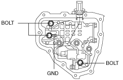
10. Remove the bolts and GND as shown, then remove the secondary control valve body.
am3uuw00002429
|
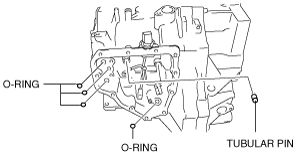
11. Remove the tubular pin and O-ring.
am3uuw00002430
|
Secondary Control Valve Body On-Vehicle Installation
1. Install the tubular pin and new O-rings to the transaxle case.
am3uuw00002430
|
2. Install the secondary control valve body.
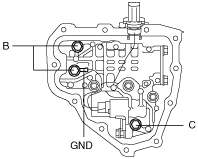
3. Tighten the bolts and GND as shown to install the secondary control valve body.
am3uuw00002431
|
Bolt length measured from below the head
|
Mark |
Length measured from below the head |
|---|---|
|
B
|
40mm {1.575 in}
|
|
C
|
50mm {1.967 in}
|
4. Connect each solenoid valve connector.
am3uuw00002432
|
Connector color (harness-side)
|
Solenoid valve |
Connector color |
|---|---|
|
Pressure control solenoid B
|
White
|
|
Shift solenoid F
|
Black
|
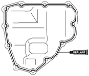
5. Apply a light coat of silicon sealant (TB1217E or equivalent) to the contact surfaces of the oil cover and transaxle case.
am3uuw00002433
|
6. Install the oil cover before the applied sealant starts to harden.
7. Add ATF. (See AUTOMATIC TRANSAXLE FLUID (ATF) REPLACEMENT [FS5A-EL].)
8. Install the aerodynamic under cover No.2. (See AERODYNAMIC UNDER COVER NO.2 REMOVAL/INSTALLATION.)
9. Install the battery tray. (See BATTERY REMOVAL/INSTALLATION [MZR 2.0, MZR 2.5].)
10. Install the battery box. (See BATTERY REMOVAL/INSTALLATION [MZR 2.0, MZR 2.5].)
11. Install the battery. (See BATTERY REMOVAL/INSTALLATION [MZR 2.0, MZR 2.5].)
12. Connect the negative battery cable.
13. Install the battery cover. (See BATTERY REMOVAL/INSTALLATION [MZR 2.0, MZR 2.5].)
14. Perform the “Mechanical System Test”. (See MECHANICAL SYSTEM TEST [FS5A-EL].)
15. Perform the “Road Test”. (See ROAD TEST [FS5A-EL].)