|
am3uuw00002440
TCM INSPECTION [FS5A-EL]
id051721293800
1. Connect the voltmeter (-) lead to body GND.
2. Measure the voltage at each terminal.
TCM Terminal Voltage (Reference)
am3uuw00002440
|
|
Terminal |
Connected to |
Test Condition |
Voltage (V) |
Inspection Item |
|---|---|---|---|---|
|
A
|
—
|
—
|
—
|
—
|
|
B
|
CAN module
|
Because this terminal is for CAN, no valid determination of terminal voltage is possible.
|
||
|
C
|
—
|
—
|
—
|
—
|
|
D
|
—
|
—
|
—
|
—
|
|
E
|
CAN module
|
Because this terminal is for CAN, no valid determination of terminal voltage is possible.
|
||
|
F
|
Down switch
|
Selector lever down-shift position
|
Below 1.0
|
• Down switch
• Related harness
|
|
Except selector lever down-shift position
|
B+
|
|||
|
G
|
Up switch
|
Selector lever up-shift position
|
Below 1.0
|
• Up switch
• Related harness
|
|
Except selector lever up-shift position
|
B+
|
|||
|
H
|
—
|
—
|
—
|
—
|
|
I
|
AT main relay
|
Ignition switch off
|
Below 1.0
|
• AT main relay
(See RELAY INSPECTION.)
• Related harness
|
|
Ignition switch ON
|
B+
|
|||
|
J
|
Battery
|
Under any condition
|
B+
|
• Battery
• Related harness
|
|
K
|
M range switch
|
M range
|
Below 1.0
|
• M range switch
• Related harness
|
|
Except M range
|
B+
|
|||
|
L
|
GND
|
Under any condition
|
Below 1.0
|
• Related harness
|
|
M
|
GND
|
Under any condition
|
Below 1.0
|
• Related harness
|
|
N
|
—
|
—
|
—
|
—
|
|
O
|
AT main relay
|
Ignition switch off
|
Below 1.0
|
• AT main relay
(See RELAY INSPECTION.)
• Related harness
|
|
Ignition switch ON
|
B+
|
|||
|
P
|
AT main relay
|
Ignition switch off
|
Below 1.0
|
• AT main relay
(See RELAY INSPECTION.)
• Related harness
|
|
Ignition switch ON
|
B+
|
|||
|
Q
|
—
|
—
|
—
|
—
|
|
R
|
—
|
—
|
—
|
—
|
|
S
|
Oil pressure switch
|
1GR
|
Below 1.0
|
• Oil pressure switch
• Related harness
|
|
2GR
|
Below 1.0
|
|||
|
3GR
|
Below 1.0
|
|||
|
4GR
|
B+
|
|||
|
5GR
|
B+
|
|||
|
T
|
Steering shift switch
|
Up switch and down switch operated
(Steering shift switch)
|
Approx. 1.8
|
• Steering shift switch
• Related harness
|
|
Up switch operated
(Steering shift switch)
|
Approx. 2.3
|
|||
|
Down switch operated
(Steering shift switch)
|
Approx. 3.0
|
|||
|
Others
|
Approx. 5.0
|
|||
|
U
|
TR switch
|
P position
|
4.3—4.8
|
• TR switch
• Related harness
|
|
R position
|
3.8—4.2
|
|||
|
N position
|
3.0—3.5
|
|||
|
D range
|
2.2—2.7
|
|||
|
M range
|
2.2—2.7
|
|||
|
V
|
TR switch, TFT sensor
|
Under any condition
|
Below 1.0
|
• Related harness
|
|
W
|
—
|
—
|
—
|
—
|
|
X
|
Steering shift switch
|
Under any condition
|
Below 1.0
|
• Related harness
|
|
Y
|
Input/turbine speed sensor (-)
|
(See Input/turbine speed sensor.)
|
• Input/turbine speed sensor
• Related harness
|
|
|
Z
|
VSS
|
(See VSS.)
|
• VSS
• Related harness
|
|
|
AA
|
TFT sensor
|
ATF temperature 20 °C {68 °F}
|
Approx. 3.3
|
• TFT sensor
• Related harness
|
|
ATF temperature 65 °C {149 °F}
|
Approx. 1.3
|
|||
|
AB
|
Input/turbine speed sensor (+)
|
(See Input/turbine speed sensor.)
|
• Input/turbine speed sensor
• Related harness
|
|
|
AC
|
Intermediate sensor
|
(See Intermediate sensor.)
|
• Intermediate sensor
• Related harness
|
|
|
AD
|
Pressure control solenoid A (+)
|
• Pressure control solenoid A
• Related harness
|
||
|
AE
|
Pressure control solenoid A (-)
|
• Pressure control solenoid A
• Related harness
|
||
|
AF
|
—
|
—
|
—
|
—
|
|
AG
|
Shift solenoid A
|
(See Shift solenoid A.)
|
• Shift solenoid A
• Related harness
|
|
|
AH
|
Shift solenoid D
|
D range 1GR
|
Below 1.0
|
• Shift solenoid D
• Related harness
|
|
D range 2GR
|
Below 1.0
|
|||
|
D range 3GR
|
Below 1.0
|
|||
|
D range 4GR
|
B+
|
|||
|
D range 5GR
|
B+
|
|||
|
AI
|
Shift solenoid F
|
D range 1GR
|
B+
|
• Shift solenoid F
• Related harness
|
|
D range 2GR
|
B+
|
|||
|
D range 3GR
|
B+
|
|||
|
D range 4GR
|
B+
|
|||
|
D range 5GR
|
Below 1.0
|
|||
|
AJ
|
Shift solenoid B
|
(See Shift solenoid B.)
|
• Shift solenoid B
• Related harness
|
|
|
AK
|
Shift solenoid E
|
TCC released
|
Below 1.0
|
• Shift solenoid E
• Related harness
|
|
TCC engaged
|
B+
|
|||
|
AL
|
Shift solenoid C
|
(See Shift solenoid C.)
|
• Shift solenoid C
• Related harness
|
|
|
AM
|
Pressure control solenoid B
|
(See Pressure control solenoid B.)
|
• Pressure control solenoid B
• Related harness
|
|
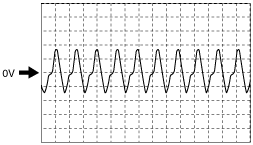
Inspection Using an Oscilloscope (Reference)
Input/turbine speed sensor
ampjjw00005641
|
VSS
aprjjw00003936
|
Intermediate sensor
aprjjw00003935
|
Pressure control solenoid A (+)
am6zzw00004855
|
Pressure control solenoid A (-)
aatjjw00005436
|
Shift solenoid A
aatjjw00005435
|
Shift solenoid B
aatjjw00005435
|
Shift solenoid C
aatjjw00005435
|
Pressure control solenoid B
am6zzw00004856
|