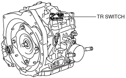
TRANSAXLE RANGE (TR) SWITCH INSPECTION [DJVA-EL]
id051901285600
-
Caution
-
• Water or foreign objects entering the connector can cause a poor connection or corrosion. Be sure not to drop water or foreign objects on the connector when disconnecting it.
Operating Inspection
1. Perform the following procedures to inspect the TR switch.
-
- (1) Verify that the starter operates only when the ignition is switched to START with the selector lever in P or N position.
- (2) Verify that the back-up lights illuminate when selected to R position with the ignition at ON.
- (3) Verify that the positions of the selector lever and the selector indicator light are aligned.
On-Vehicle Inspection
1. Perform the following procedures.
- (1) Remove the battery cover. (See BATTERY REMOVAL/INSTALLATION [MZR 1.5, MZR 1.6].)
- (2) Disconnect the negative battery cable.
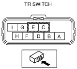
- (3) Disconnect the TR switch connector.
-
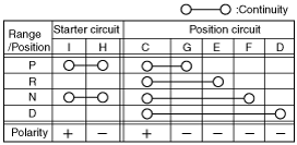
2. Inspect continuity as indicated in the table.
-
Wiring Harness Inspection
1. Perform the following procedures.
- (1) Remove the battery cover. (See BATTERY REMOVAL/INSTALLATION [MZR 1.5, MZR 1.6].)
- (2) Disconnect the negative battery cable.
- (3) Remove the dashboard under cover. (See DASHBOARD UNDER COVER REMOVAL/INSTALLATION.)
- (4) Remove the side wall. (See SIDE WALL REMOVAL/INSTALLATION.)
- (5) Partially peel back the floor covering. (See FLOOR COVERING REMOVAL/INSTALLATION.)
- (6) Disconnect the TCM and TCM bracket as a single unit. (See TCM REMOVAL/INSTALLATION [DJVA-EL].)
2. Switch the ignition to ON (Engine off).
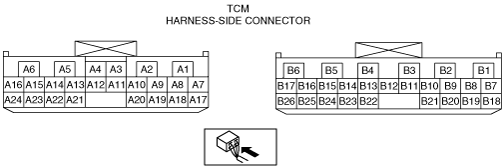
3. Inspect for continuity between TR switch and TCM using a tester.
-
• If there is any malfunction, repair or replace the wiring harness.
TR switch specification
|
Terminal
|
Specification (V)
|
|
P position
|
R position
|
N position
|
D range
|
|
B20—GND
|
B+
|
0V
|
0V
|
0V
|
|
B1—GND
|
0V
|
B+
|
0V
|
0V
|
|
B8—GND
|
0V
|
0V
|
B+
|
0V
|
|
B7—GND
|
0V
|
0V
|
0V
|
B+
|