|
am3zzw00012305
REAR VEHICLE MONITORING CONTROL MODULE INSPECTION
id092200014700
1. Disconnect the negative battery cable.
(See BATTERY REMOVAL/INSTALLATION [MZR 2.0, MZR 2.5].)
2. Remove the rear combination light. (See REAR COMBINATION LIGHT REMOVAL/INSTALLATION.)
3. Remove the rear bumper. (See REAR BUMPER REMOVAL/INSTALLATION.)
4. Connect the negative battery cable.
5. Measure the voltage at each terminal is as indicated in the Terminal Voltage Tables.
Terminal Voltage Table (Reference)
Rear vehicle monitoring control module (RH)
am3zzw00012305
|
|
Terminal |
Signal |
Connected to |
Measurement condition |
Voltage (V) |
Inspection item(s) |
|
|---|---|---|---|---|---|---|
|
A
|
CAN2_L
|
Rear vehicle monitoring CM (LH)
|
Terminal used for communication therefore determination based on terminal voltage is not possible.
|
|||
|
C
|
CAN2_H
|
Rear vehicle monitoring CM (LH)
|
Terminal used for communication therefore determination based on terminal voltage is not possible.
|
|||
|
D
|
RVM switch signal
|
RVM switch
|
Switch the ignition to ON
|
RVM switch pressed
|
1.0 or less
|
• RVM switch
• Related wiring harness
|
|
RVM switch not pressed
|
+B
|
|||||
|
F
|
Power supply
|
METER 15 A fuse
|
Switch the ignition to ON
|
+B
|
• METER 15 A fuse
• Related wiring harness
|
|
|
Switch the ignition to off
|
1.0 or less
|
|||||
|
H
|
Ground
|
Body ground
|
Under any condition
|
1.0 or less
|
• Related wiring harness
|
|
|
I
|
CAN_L
|
CAN system related module
|
Terminal used for communication therefore determination based on terminal voltage is not possible.
|
|||
|
L
|
CAN_H
|
CAN system related module
|
Terminal used for communication therefore determination based on terminal voltage is not possible.
|
|||
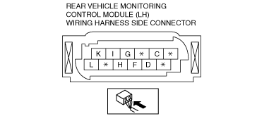
Terminal Voltage Table (Reference)
Rear vehicle monitoring control module (LH)
am3zzw00012306
|
|
Terminal |
Signal |
Connected to |
Measurement condition |
Voltage (V) |
Inspection item(s) |
|
|---|---|---|---|---|---|---|
|
C
|
RVM warning indicator light ground signal (RH)
|
RVM warning indicator light (RH)
|
Under any condition
|
1.0 or less
|
• RVM warning indicator light LED (RH)
• Related wiring harness
|
|
|
D
|
RVM warning indicator light signal (RH)
|
RVM warning indicator light (RH)
|
Switch the ignition to ON
|
LED off
|
1.0 or less
|
• RVM warning indicator light LED (RH)
• Related wiring harness
|
|
LED on
|
3.0—5.0
|
|||||
|
F
|
Power supply
|
METER 15 A fuse
|
Switch the ignition to ON
|
+B
|
• METER 15 A fuse
• Related wiring harness
|
|
|
Switch the ignition to off
|
1.0 or less
|
|||||
|
G
|
RVM warning indicator light ground signal (LH)
|
RVM warning indicator light (LH)
|
Under any condition
|
1.0 or less
|
• RVM warning indicator light LED (LH)
• Related wiring harness
|
|
|
H
|
Ground
|
Body ground
|
Under any condition
|
1.0 or less
|
• Related wiring harness
|
|
|
I
|
CAN2_L
|
Rear vehicle monitoring CM (RH)
|
Terminal used for communication therefore determination based on terminal voltage is not possible.
|
|||
|
K
|
RVM warning indicator light signal (LH)
|
RVM warning indicator light (LH)
|
Switch the ignition to ON
|
LED off
|
1.0 or less
|
• RVM warning indicator light (LH)
• Related wiring harness
|
|
LED on
|
3.0—5.0
|
|||||
|
L
|
CAN2_H
|
Rear vehicle monitoring CM (RH)
|
Terminal used for communication therefore determination based on terminal voltage is not possible.
|
|||