DTC P0841


id050200809500

DTC P0841

Oil pressure switch circuit malfunction

DETECTION CONDITION
•  When DTC P0731, P0732, P0733 and P0734 are not output and 10 s or more has passed.
―  When all the conditions below are satisfied while driving in 1GR, 2GR or 3GR
•  ATF temperature 20 °C {68 °F} or more
•  Oil pressure switch OFF
•  Revolution ratio of forward clutch drum revolution to differential gear case revolution below 0.91 or more than 3.08
•  None of the following present: DTC P0500, P0706, P0707, P0708, P0712, P0713, P0715, P0751, P0752, P0753, P0756, P0757, P0758, P0761, P0762, P0763, P0766, P0767, P0768, P0771, P0772, P0773
―  When all conditions below are satisfied while driving in 4GR
•  ATF temperature 20 °C {68 °F} or more
•  Oil pressure switch ON
•  Revolution ratio of forward clutch drum revolution to differential gear case revolution below 0.64 or more than 0.82
•  None of the following present: DTC P0500, P0706, P0707, P0708, P0712, P0713, P0715, P0751, P0752, P0753, P0756, P0757, P0758, P0761, P0762, P0763, P0766, P0767, P0768, P0771, P0772, P0773
Diagnostic support note:
•  This is a continuous monitor (CCM).
•  The MIL illuminates if the PCM detects the above malfunction condition in two consecutive drive cycles or in one drive cycle while the DTC for the same malfunction has been stored in the PCM.
•  A PENDING CODE is not available.
•  FREEZE FRAME DATA is not available.
•  The AT warning light illuminates.
•  The DTC is stored in the PCM memory.
POSSIBLE CAUSE
•  Oil pressure switch malfunction
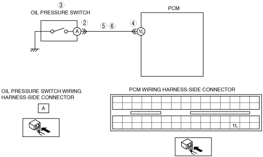
•  Open circuit in wiring harness between oil pressure switch terminal A and PCM terminal 1L
•  Short to ground in wiring harness between oil pressure switch terminal A and PCM terminal 1L
•  Damaged connector between oil pressure switch and PCM
•  PCM malfunction

Diagnostic procedure

STEP

INSPECTION

ACTION

1
VERIFY FREEZE FRAME DATA HAS BEEN RECORDED
•  Has the FREEZE FRAME DATA been recorded?
Yes
Go to the next step.
No
Record the FREEZE FRAME DATA on the repair order, then go to the next step.
2
INSPECT OIL PRESSURE SWITCH CONNECTOR FOR POOR CONNECTION
•  Disconnect the shift oil pressure switch connector.
•  Inspect for poor connection (such as damaged/pulled-out pins, corrosion).
•  Is the connection normal?
Yes
Go to the next step.
No
Repair or replace the connector and/or terminals, then go to Step 7.
3
INSPECT CONTINUITY
•  Inspect for continuity between oil pressure switch terminal A (part-side) and body ground.
•  Is there continuity?
Yes
Replace the oil pressure switch, then go to Step 7.
No
Go to the next step.
4
INSPECT PCM CONNECTOR FOR POOR CONNECTION
•  Disconnect the PCM connector.
•  Inspect for poor connection (such as damaged/pulled-out pins, corrosion).
•  Is the connection normal?
Yes
Go to the next step.
No
Repair or replace the connector and/or terminals, then go to Step 7.
5
INSPECT OIL PRESSURE SWITCH CIRCUIT FOR OPEN CIRCUIT
•  Inspect for continuity between PCM terminal 1L (wiring harness-side) and oil pressure switch terminal A (wiring harness-side).
•  Is there continuity between terminals?
Yes
Go to the next step.
No
Repair or replace the wiring harness, then go to Step 7.
6
INSPECT PCM CIRCUIT FOR SHORT TO GROUND
•  Turn the ignition switch to the LOCK position.
•  Inspect for continuity between PCM terminal 1L (wiring harness-side) and body ground.
•  Is there continuity?
Yes
Repair or replace the wiring harness, then go to the next step.
No
Replace the oil pressure switch, then go to the next step.
7
VERIFY TROUBLESHOOTING OF DTC P0841 COMPLETED
•  Make sure to reconnect all the disconnected connectors.
•  Clear the DTC from the memory using the WDS or equivalent.
•  Drive the vehicle and make sure that gears shift smoothly from 1GR to 4GR.
•  Are any DTCs present?
Yes
Replace the PCM, then go to the next step.
No
No concern is detected. Go to the next step.
8
VERIFY AFTER REPAIR PROCEDURE
•  Perform the “After Repair Procedure”.
•  Are any DTCs present?
Yes
Go to the applicable DTC inspection.
(See DTC TABLE.)
No
DTC troubleshooting completed.