 |
am6zzw00017938
TIMING CHAIN REMOVAL/INSTALLATION [MZR 2.0 DISI]
id011007801000
1. Disconnect the negative battery cable.
2. Remove the plug hole plate. (See PLUG HOLE PLATE REMOVAL/INSTALLATION [MZR 2.0 DISI].)
3. Disconnect the wiring harness.
4. Remove the high pressure fuel pump and high pressure fuel pump cover. (See HIGH PRESSURE FUEL PUMP REMOVAL/INSTALLATION [MZR 2.0 DISI].)
5. Remove the ignition coils. (See IGNITION COIL REMOVAL/INSTALLATION [MZR 2.0 DISI].)
6. Remove the spark plugs. (See SPARK PLUG REMOVAL/INSTALLATION [MZR 2.0 DISI].)
7. Disconnect the ventilation hose from the cylinder head cover.
8. Remove the front wheel and tire. (RH) (See GENERAL PROCEDURES (SUSPENSION).)
9. Remove the aerodynamic under cover No.2. (See AERODYNAMIC UNDER COVER NO.2 REMOVAL/INSTALLATION.)
10. Set the front mudguard (RH) out of the way. (See FRONT MUDGUARD REMOVAL/INSTALLATION.)
11. Remove the splash shield (RH). (See SPLASH SHIELD REMOVAL/INSTALLATION.)
12. Loosen the water pump pulley bolts and remove the drive belt. (See DRIVE BELT REMOVAL/INSTALLATION [MZR 2.0 DISI].)
13. Remove the crankshaft position (CKP) sensor. (See CRANKSHAFT POSITION (CKP) SENSOR REMOVAL/INSTALLATION [MZR 2.0 DISI].)
14. Disconnect the drive shaft (RH) from joint shaft, set the drive shaft (RH) out of the way. (ATX) (See DRIVE SHAFT REMOVAL/INSTALLATION.)
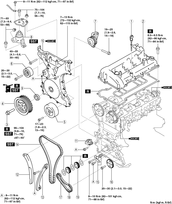
15. Remove in the order indicated in the table.
16. Install in the reverse order of removal.
17. Start the engine. And inspect and adjust the following:
am6zzw00017938
|
|
1
|
Dipstick
|
|
2
|
Cylinder head cover
|
|
3
|
Crankshaft pulley lock bolt
|
|
4
|
Crankshaft pulley
|
|
5
|
Water pump pulley
|
|
6
|
Drive belt idler pulley
|
|
7
|
Drive belt idler pulley
|
|
8
|
No.3 engine mount
|
|
9
|
Front oil seal
|
|
10
|
Engine front cover
|
|
11
|
Chain tensioner
(See Chain Tensioner Removal Note.)
|
|
12
|
Tensioner arm
|
|
13
|
Chain guide
|
|
14
|
Timing chain
|
|
15
|
Oil pump chain tensioner
|
|
16
|
Oil pump driven sprocket
|
|
17
|
Oil pump chain
|
|
18
|
Crankshaft sprocket
|
|
19
|
Oil pump drive sprocket
|
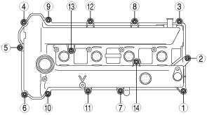
Cylinder Head Cover Removal Note
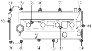
1. Loosen the cylinder head cover bolts in the order shown in the figure.
am6zzw00012563
|
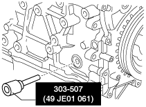
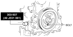
Crankshaft Pulley Lock Bolt Removal Note
1. Rotate the crankshaft in the direction of the engine rotation and remove the cylinder block lower blind plug when the No. 1 cylinder is at the point prior to top dead center (TDC) of compression, then install the SST.
am6zzw00012564
|
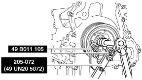
2. Rotate the crankshaft in the direction of the engine rotation so that the No.1 piston is at TDC of the compression stroke. (Until the counterweight contacts SST and stops.)
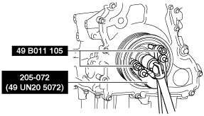
3. Hold the crankshaft pulley by using the SSTs.
am6zzw00012565
|
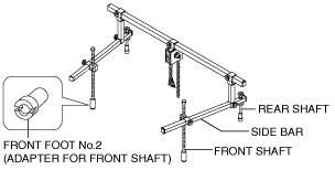
No.3 Engine Mount Removal Note
Oil pan is removed
1. Install the SST using the following procedures.
am6zzw00012566
|
am6zzw00000925
|
am6zzw00000926
|
2. Support the engine using the SST.
am6zzw00000927
|
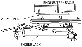
Oil pan is not removed
1. Support the engine (oil pan) using a commercially available engine lifter.
acxaaw00001645
|
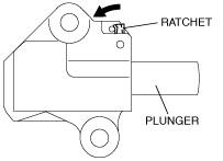
Chain Tensioner Removal Note
1. Press the timing chain tensioner ratchet to the left using a thin flathead screwdriver (precision screwdriver) to unlock the plunger.
am6zzw00012567
|
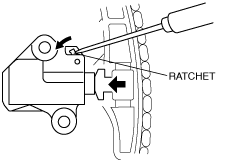
2. Slowly press the plunger back in the direction shown in the figure while pressing the ratchet.
am6zzw00012568
|
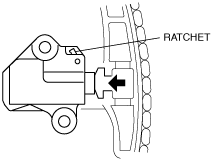
3. Release the ratchet with the plunger still pressed down.
am6zzw00012569
|
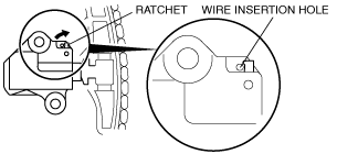
4. Press-in the plunger until the ratchet position is as indicated in the figure, and then insert the wire to lock the plunger.
am6zzw00012570
|
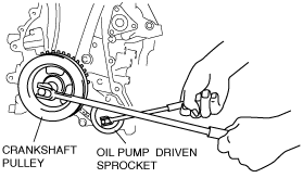
Oil Pump Driven Sprocket Removal Note
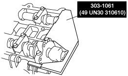
1. Temporarily install the crankshaft pulley and crankshaft pulley lock bolt to the crankshaft, and lock the oil pump against rotation as shown in figure.
am6zzw00012571
|
2. Remove the oil pump driven sprocket, and then remove the crankshaft pulley and crankshaft pulley lock bolt.
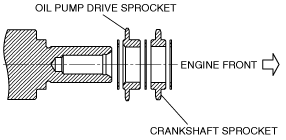
Oil Pump Drive Sprocket Installation Note
1. The oil pump drive sprocket has the assembly direction as shown in the figure.
am6zzw00012572
|
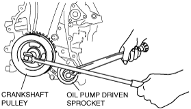
Oil Pump Driven Sprocket Installation Note
1. Temporarily install the crankshaft pulley and crankshaft pulley lock bolt to the crankshaft, and lock the oil pump against rotation as shown in figure.
am6zzw00012573
|
2. Install the oil pump driven sprocket, and then remove the crankshaft pulley and crankshaft pulley lock bolt.
Timing Chain Installation Note
1. Install the SST to the camshaft as shown in the figure.
acxuuw00000234
|
2. Install the timing chain.
3. Remove the wire or paper clip from the chain tensioner piston and apply tension to the timing chain.
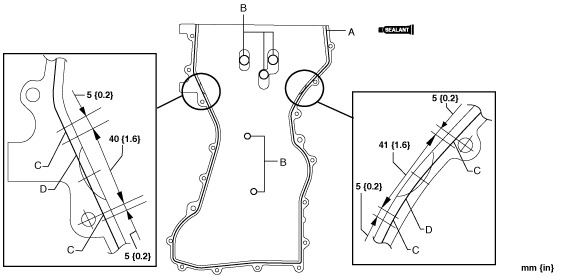
Engine Front Cover Installation Note
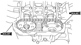
1. Apply silicone sealant to the engine front cover as shown.
am6zzw00012574
|
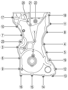
2. Tighten the engine front cover installation bolts in the order shown in the figure.
am6zzw00012575
|
|
No. |
Tightening torque |
|---|---|
|
1―18
|
8—11 N·m {82—112 kgf·cm, 71—97 in·lbf}
|
|
19―22
|
40—55 N·m {4.1—5.6 kgf·m, 30—40 ft·lbf}
|
|
23
|
20—30 N·m {2.1—3.0 kgf·m, 15—22 ft·lbf}
|
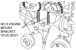
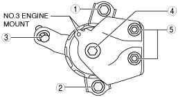
No.3 Engine Mount Installation Note
1. Tighten the No.3 engine mount stud bolts.
am6zzw00012576
|
2. Temporarily tighten the No.3 engine mount installation bolts and nuts.
3. Tighten the No.3 engine mount installation bolts and nuts in the order shown in the figure.
am6zzw00005601
|
|
No. |
Tightening torque |
|---|---|
|
1—3
|
71—93 N·m {7.3—9.4 kgf·m, 53—68 ft·lbf}
|
|
4, 5
|
75—104 N·m {7.7—10 kgf·m, 56—76 ft·lbf}
|
Crankshaft Pulley Lock Bolt Installation Note
1. Install the SST to the camshaft as shown in the figure.
acxuuw00000234
|
2. Verify that the No.1 cylinder is at TDC of the compression stroke. (The position counterweight contacts the SST.)
3. To position the crankshaft pulley, temporarily tighten it and, using a suitable bolt (M6 X 1.0), fix the crankshaft pulley to the engine front cover.
am6zzw00012577
|
4. Hold the crankshaft pulley using the SSTs.
am6zzw00012578
|
5. Tighten the crankshaft pulley lock bolt in the order shown in the following two steps using the SST (49 D032 316).
6. Remove the bolt (M6 X 1.0) installed to the crankshaft pulley.
7. Remove the SST from the camshaft.
8. Remove the SST installed in the cylinder block lower blind plug hole.
9. Rotate the crankshaft clockwise two turns and inspect the valve timing.
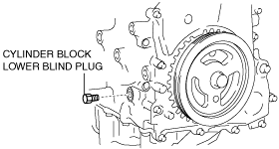
10. Install the cylinder block lower blind plug.
am6zzw00012579
|
Cylinder Head Cover Installation Note
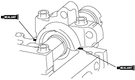
1. Apply silicone sealant to the areas shown in the figure.
am6zzw00012580
|
am6zzw00012581
|
2. Tighten the cylinder head cover bolts in the order shown in the figure.
am6zzw00012582
|