|
am6zzw00001690
STEERING WHEEL AND COLUMN REMOVAL/INSTALLATION [WITH ADVANCED KEYLESS ENTRY AND PUSH BUTTON START SYSTEM]
id0613008014c2
1. Remove the front scuff plate (driver-side). (See FRONT SCUFF PLATE REMOVAL/INSTALLATION.)
2. Remove the front side trim (driver-side). (See FRONT SIDE TRIM REMOVAL/INSTALLATION.)
3. Remove the upper panel. (See UPPER PANEL REMOVAL/INSTALLATION.)
4. Remove the decoration panel (driver-side). (See DECORATION PANEL REMOVAL/INSTALLATION.)
5. Remove the bonnet release lever knob. (See BONNET LATCH AND RELEASE LEVER REMOVAL/INSTALLATION.)
6. Remove the lower panel. (See LOWER PANEL REMOVAL/INSTALLATION.)
7. Remove in the order indicated in the table.
8. Install in the reverse order of removal.
9. If the steering lock component is replaced, perform programming for the immobilizer system related parts. (See IMMOBILIZER SYSTEM-RELATED PARTS PROGRAMMING [ADVANCED KEYLESS ENTRY AND PUSH BUTTON START SYSTEM].)
10. After installation, set the EPS system to the neutral position. (See EPS SYSTEM NEUTRAL POSITION SETTING.)
am6zzw00001690
|
|
1
|
Driver-side air bag module
|
|
2
|
Lockbolt
|
|
3
|
Steering wheel
(See Steering Wheel Removal Note.)
|
|
4
|
Column cover
|
|
5
|
Clock spring, combination switch
|
|
6
|
Steering shaft cover
|
|
7
|
Joint Bolt
|
|
8
|
Steering shaft component
|
|
9
|
Steering lock mounting bolt
|
|
10
|
Steering lock upper cover
|
|
11
|
Steering lock component
|
|
12
|
Cover
|
|
13
|
Coil antenna
|
|
14
|
Coil attachment
|
|
15
|
Steering lock
|
|
16
|
Steering shaft
|
|
17
|
Steering dust cover
|
Steering Wheel Removal Note
1. Set the wheels in the straight-ahead position.
2. Remove the steering wheel using any commercially available puller.
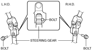
Joint Bolt (Intermediate Shaft) Removal Note
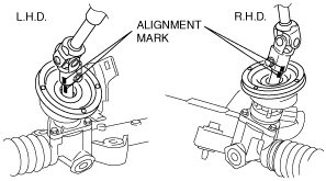
1. Place alignment marks on the intermediate shaft joint, and the steering gear for proper installation.
am6zzw00001691
|
2. Remove the joint bolt and detach the intermediate shaft from the steering gear.
Steering Shaft Component Removal Note
1. Lock the adjusting lever.
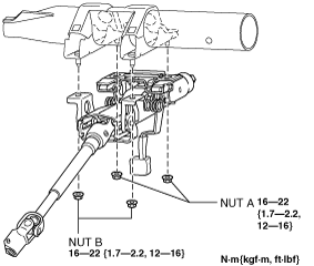
2. Remove the nut, and then remove the steering shaft component from the dashboard member.
Steering Lock Mounting Bolt, Steering Lock Component Removal Note
1. Make a groove in the heads of the steering lock mounting bolts using a chisel and hammer.
am6zzw00001975
|
2. Remove the bolt using a flathead screwdriver, then remove the steering lock component from the steering shaft.
Steering Dust Cover Installation Note
1. Install the steering dust cover to the dashboard lower panel.
2. Verify that the lip area of the steering dust cover is securely installed to the steering gear, and the tabs are installed to the dashboard lower panel.
am6zzw00002015
|
Steering Lock Component, Steering Lock Mounting Bolt Installation Note
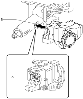
1. Assemble section A of the steering lock component to the section B of the steering shaft.
am6zzw00001693
|
2. Temporarily install the steering lock component to the steering shaft using a new steering lock mounting bolt.
3. Tighten the steering lock mounting bolt until the head breaks off.
am6zzw00001976
|
Steering Shaft Component Installation Note
1. Verify that the adjusting lever is in the LOCK position.
2. Temporarily install the steering shaft component to the dashboard member using nuts A and B.
am6zzw00001952
|
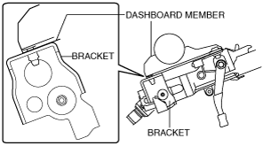
3. Verify that there is no clearance between the steering column component bracket and the dashboard member.
am6zzw00006154
|
4. Tighten the nuts in the order of nut A and nut B.
Joint Bolt (Intermediate Shaft) Installation Note
1. Align the marks made during removal and install the steering intermediate shaft joint to the steering gear.
am6zzw00001691
|
2. After temporarily installing the joint bolt to the intermediate shaft joint, shake the intermediate shaft up and down to verify that the joint bolt is installed to the groove of the steering gear.
am6zzw00001964
|
3. Tighten the joint bolt to the specified torque.
Steering Wheel, Lockbolt Installation Note
1. Set the vehicle wheels in the straight-ahead position, and install the steering wheel using a new lock bolt.