 |
am6zzw00004565
CLUTCH UNIT REMOVAL/INSTALLATION [A26M-R]
id0510m8800300
1. Disconnect the negative battery cable. (See BATTERY REMOVAL/INSTALLATION [MZR-CD 2.2].)
2. Remove the following parts:
3. Drain the engine coolant. (See ENGINE COOLANT REPLACEMENT [MZR-CD 2.2].)
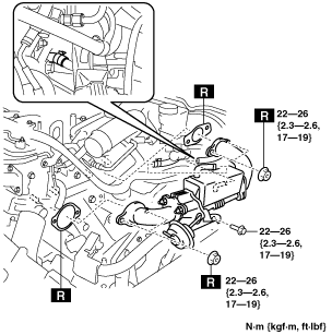
4. Disconnect the vacuum hose. (See EGR COOLER REMOVAL/INSTALLATION [MZR-CD 2.2].)
5. Remove the EGR cooler and EGR bypass valve component and EGR cooler bracket. (See EGR COOLER REMOVAL/INSTALLATION [MZR-CD 2.2].)
am6zzw00004565
|
6. Remove the front tires. (See GENERAL PROCEDURES (SUSPENSION).)
7. Remove the splash shields. (See SPLASH SHIELD REMOVAL/INSTALLATION.)
8. Remove the aerodynamic under cover No.2. (See AERODYNAMIC UNDER COVER NO.2 REMOVAL/INSTALLATION.)
9. Remove the aerodynamic under cover No.1. (See AERODYNAMIC UNDER COVER NO.1 REMOVAL/INSTALLATION.)
10. Remove the transverse member. (See TRANSVERSE MEMBER REMOVAL/INSTALLATION.)
11. Remove the hanger on the oxidation catalytic converter (built-in diesel particulate filter) side and set the hanger aside.
12. Remove the vacuum chamber installation nuts and set the vacuum chamber aside so that it is out of the way. (See INTAKE-AIR SYSTEM REMOVAL/INSTALLATION [MZR-CD 2.2].)
13. Remove the joint pipe bracket. (See EXHAUST SYSTEM REMOVAL/INSTALLATION [MZR-CD 2.2].)
14. Remove the auto leveling sensor. (front)(See AUTO LEVELING SENSOR REMOVAL/INSTALLATION.)
15. Remove the steering shaft cover. (See STEERING GEAR AND LINKAGE REMOVAL/INSTALLATION [L.H.D.].)(See STEERING GEAR AND LINKAGE REMOVAL/INSTALLATION [R.H.D.].)
16. Remove the joint bolt for the steering shaft and disconnect the steering shaft from the steering gear and linkage side. (See STEERING GEAR AND LINKAGE REMOVAL/INSTALLATION [L.H.D.].)(See STEERING GEAR AND LINKAGE REMOVAL/INSTALLATION [R.H.D.].)
17. Drain the transaxle oil into a suitable container. (See TRANSAXLE OIL REPLACEMENT [A26M-R].)
18. Remove the manual transaxle. (See MANUAL TRANSAXLE REMOVAL/INSTALLATION [A26M-R].)
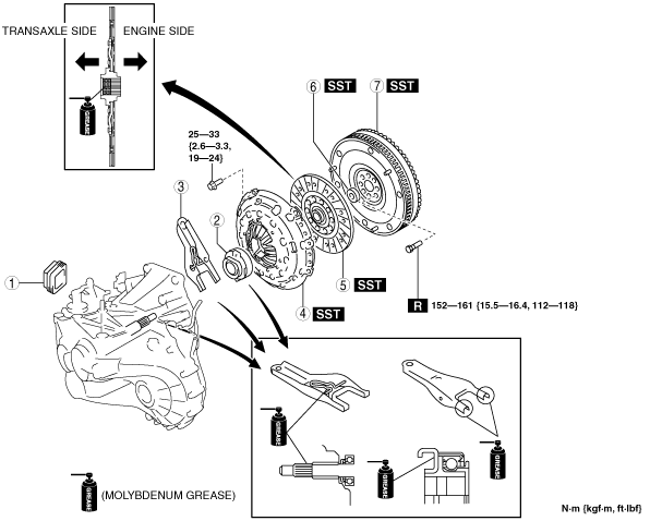
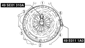
19. Remove in the order indicated in the table.
20. Install in the reverse order of removal.
21. Perform the auto leveling system initialization. (See AUTO LEVELING SYSTEM INITIALIZATION.)
22. Add the specified amount of specified transaxle oil. (See TRANSAXLE OIL REPLACEMENT [A26M-R].)
am6zzw00007102
|
|
1
|
Boot
|
|
2
|
Clutch release collar
|
|
3
|
Clutch release fork
|
|
4
|
Clutch cover
|
|
5
|
Clutch disc
|
|
6
|
Pilot bearing
(See Pilot Bearing Removal Note.)
|
|
7
|
Flywheel
(See Flywheel Removal Note.)
(See Flywheel Installation Note.)
|
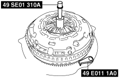
Clutch Cover and Disc Removal Note
1. Install the SSTs.
am6zzw00007103
|
2. Loosen each bolt one turn at a time in a crisscross pattern until spring tension is released.
3. Remove the clutch cover and disc.
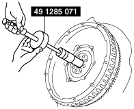
Pilot Bearing Removal Note
1. Use the SST to remove the pilot bearing.
am6zzw00007104
|
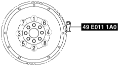
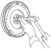
Flywheel Removal Note
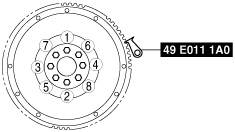
1. Hold the flywheel using the SST.
am6zzw00007105
|
2. Loosen the lock bolts uniformly in the order of the numbers shown in the figure and remove the flywheel.
Flywheel Installation Note
1. Clean the crankshaft thread holes.
2. Install the flywheel to the crankshaft.
3. When reusing the bolts, clean threads and hole, then apply locking compound to the threads.
4. Hand-tighten the new flywheel lock bolts.
5. Install the SST to the flywheel.
am6zzw00007106
|
6. Gradually tighten the flywheel lock bolts in a crisscross pattern.
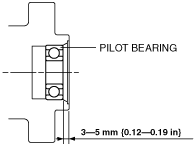
Pilot Bearing Installation Note
1. Install the pilot bearing using the corresponding 20 mm {0.79 in} side of a Snap-on brand millimeter size bushing driver set A160M adapter A160M7 (20—22 mm {0.79—0.86 in}) or substitution tool.
am6zzw00007107
|
2. Press-fit the pilot bearing to the position which is 3—5 mm {0.12—0.19 in} from the crankshaft end.
am6zzw00007108
|
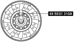
Clutch Disc Installation Note
1. Clean the splines of the clutch disc and the main drive gear with a brush.
2. Spread a thin layer of clutch grease on the splines.
3. Hold the clutch disc position using the SST.
am6zzw00007109
|
Clutch Cover Installation Note
1. Install the SSTs.
am6zzw00007110
|
2. Tighten the bolts uniformly in the order of the numbers shown in the figure and install the clutch cover.